Raspberry PI extension board - RasPiEx
Monday, February 4, 2013
The RaspberryPI project tries to encourage people to learn programming or start realizing their project ideas. With it’s low price and easy setup one can start developing right away. Thats for software. But the RaspberryPI also provides some ways for hardware extensions. Unfortunately most people think that hardware development is hard and complex. Sure it is different from software development but not so much.
This project describes an extension board wich provides the following functions:
- 3V and 5V I2C ports
- I2C Temperature sensor
- Battery backed real time clock (RTC)
- A RS232 serial port
And all this is not hard to build. No special tools besides a soldering iron and some pliers are needed. Also there is no need to produce a custom printed circuit board. No etching and drilling required. A simple piece of perfboard (13 x 21 holes = 5cm x 12cm ???) is used.
The functions in detail:
3V and 5V I2C ports
The RasPI works with 3.3V. This is as long as you connect only 3V devices to the I2C bus no problem. Connecting 5V parts either work or wont work. In the worst case you could damage your RasPI. So there is a circuit available on the RasPiEx which converts the 3V I2C port into a 5V port. Now you can connect 3V and 5V ports as you like.
Using the RasPI’s I2C port
To use the RasPi’s I2C port some prerequisites have to be met. First you must load the corresponding I2C kernel modules. After this you can use the bus with whatever programming language you prefere. We will use python.
If you Raspbian as operating system check /etc/modprobe.d/raspi-blacklist.conf and comment “blacklist i2c-bcm2708” by running
sudo nano /etc/modprobe.d/raspi-blacklist.conf
and adding a # (if its not there).
#blacklist i2c-bcm2708
If you’re running Wheezy add the following lines to /etc/modules
i2c-dev
i2c-bcm2708
and then reboot.
Now install some I2C utilities and the python module:
sudo apt-get install python-smbus
sudo apt-get install i2c-tools
So lets check if our extension board and the I2C components on it are recognized by the raspberry. If you have an Original Raspberry Pi (Sold before October 2012) - the I2C is port 0:
sudo i2cdetect -y 0
If you have a second rev Raspberry Pi, the I2C is on port 1:
sudo i2cdetect -y 1
This will search /dev/i2c-0 or /dev/i2c-1 for all address. You should see the following output:
     0  1  2  3  4  5  6  7  8  9  a  b  c  d  e  f
00: -- -- -- -- -- -- -- -- -- -- -- -- -- -- -- --
10: -- -- -- -- -- -- -- -- -- -- -- -- -- -- -- --
20: -- -- -- -- -- -- -- -- -- -- -- -- -- -- -- --
30: -- -- -- -- -- -- -- -- -- -- -- -- -- -- -- --
40: -- -- -- -- -- -- -- -- 48 -- -- -- -- -- -- --
50: -- -- -- -- -- -- -- -- -- -- -- -- -- -- -- --
60: -- -- -- -- -- -- -- -- 68 -- -- -- -- -- -- --
70: -- -- -- -- -- -- -- -- -- -- -- -- -- -- -- --
Where 0×48 is the address of the DS1624 temperature sensor and 0×68 from the DS1307 real time clock.
Ich all went well so far the extension board seems to work and we can start using the components on it.
I2C Temperature sensor
The DS1624 is a I2C temperature sensor connected to the 3V I2C bus. The pins 5,6,7 are the address pins and are connected to ground giving it the I2C address 0×48. Using this address you can read the current temperature using the following python script and display it on the console:
#!/usr/bin/python
import smbus
import time
DS1624A0_ADDR = 0x48
DS1624_READ_TEMP = 0xAA
DS1624_START = 0xEE
DS1624_STOP = 0x22
bus = smbus.SMBus(0)
address = DS1624A0_ADDR
def start():
	bus.write_byte(address, DS1624_START);
def stop():
	bus.write_byte(address, DS1624_STOP);
def read():
	temp1 = bus.read_word_data(address, DS1624_READ_TEMP);
	temp_l = (temp1 & 0xFF00) >> 8;
	temp_h = temp1 & 0x00FF;
	temp_l = temp_l >> 3;
	if (temp_h & 0x80) == 0x80:
		temp_l = (~temp_l) + 1;
	return temp_h + ( 0.03125 * temp_l);
start();
time.sleep(1);
temperature = read();
print "%02.02f" % temperature;
Save it as ds1624 so you can use it for example for temperature logging described in this post.
Battery backed real time clock (RTC)
Every time you boot up your RasPI it tries to set its software clock from a time server on the internet because he has no hardware clock. If there is no network connection or time server available it will use the Linux kernels build time to set its date and time. So in this case you have to change the date and time by hand. The RasPiEx contains a DS1307 real time clock on the 5V I2C bus as it is a 5V device. There is also a lithium 3V CR2032 battery available keeping the DS1307 running when the RasPI is turned off for the next couple years.
To enable the clock add the following line to /etc/modules
rtc-ds1307
by using the following command.
sudo nano /etc/modules
Next edit /etc/rc.conf and add these line before exit 0
echo ds1307 0x68 > /sys/class/i2c-adapter/i2c-0/new_device
hwclock -s
using
sudo nano /etc/rc.conf
Note: Use either i2c-0 or i2c-1 depending on your raspberrys revision as described at the DS1624 temperature sensor.
Reading the time from the DS1307 can be done using the following command:
sudo hwclock -r
The command line parameter -s sets the hardware clock to the date of the system clock. So the first time you should sync your time over the internet and then write this date/time with -s to the hardware cock.
A RS232 serial port
Under normal conditions you would not need the RaspI’s RS232 serial port. But if you would like to connect things like modems, serial printers or for example a PC with a terminal program like Hyperterm then use this port. The MAX3232 converts from a ‘real’ serial ports +/-12V into the RasPI’s 3V. So don’t try to connect a RS232 serial port directly to the RasPI’s serial port without such a converter.
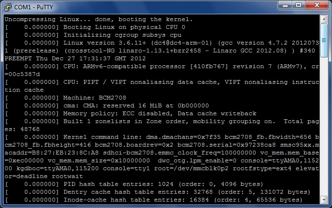
When using a PC terminal program like putty connected to the raspberrys RS232 port using 115200 baud, 8 data bits and 1 stop bit you should see the following lines during booting your raspberry:
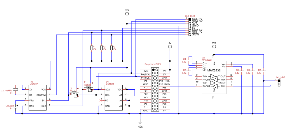
Schematic
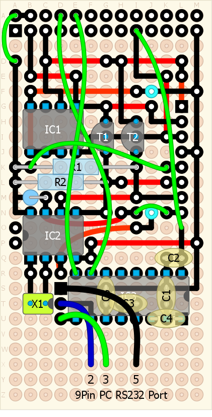
The board
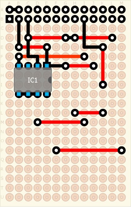
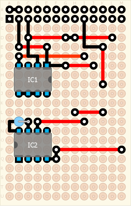
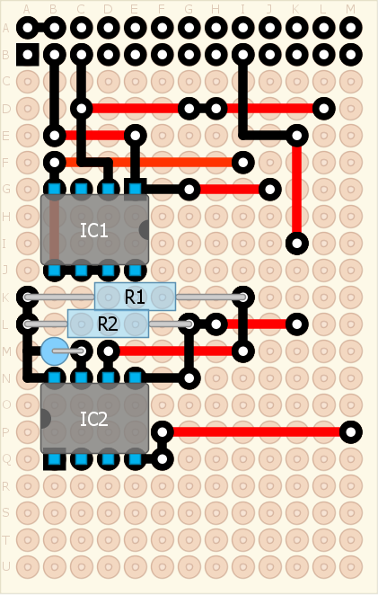
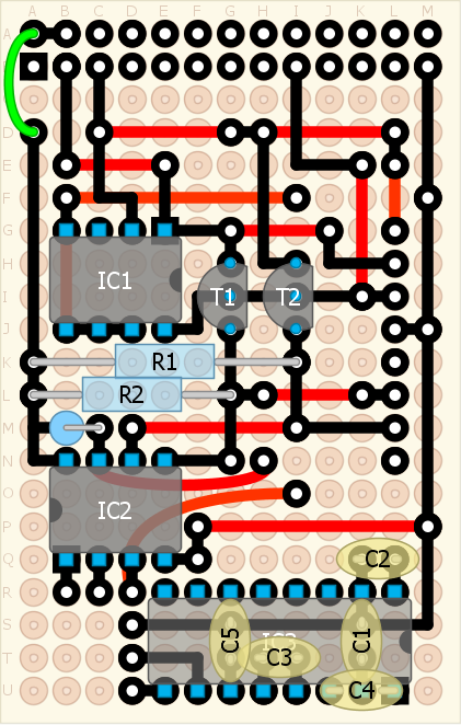
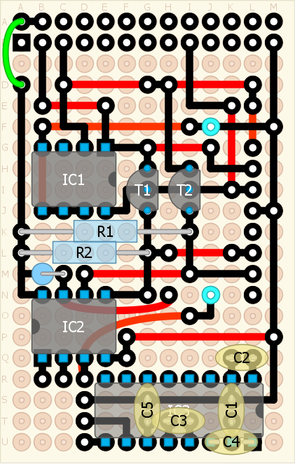
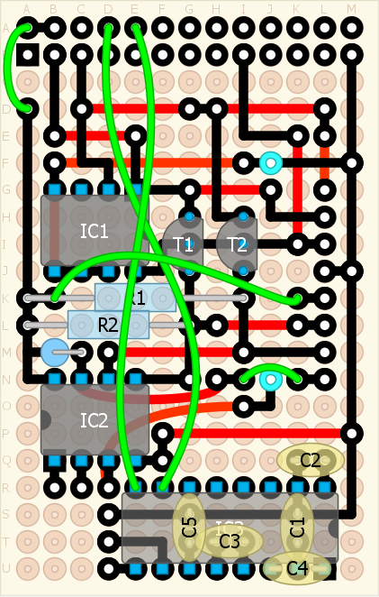
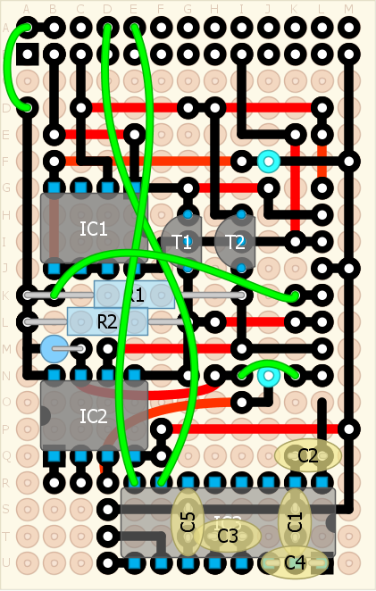
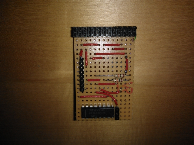
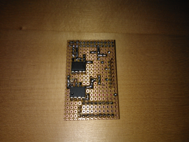
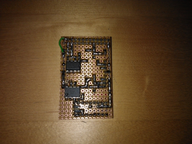
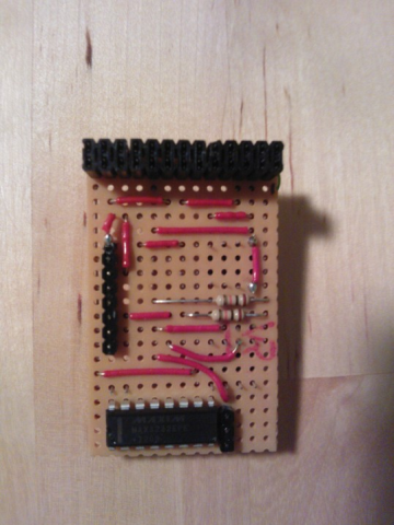
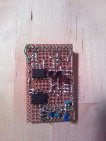
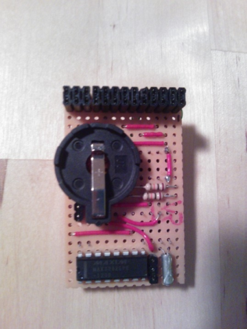
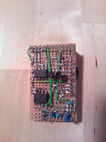
As already said this project does not use a custom made printed circuit board especially designed, etched and drilled. Instead it uses a simple piece of perfboard. Build it by following this step by step guide. The red and green traces are insulated wires whereas the black traces are blank wires soldered onto the perfboard. The red wires are placed on the non copper side whereas all other wires are placed on the copper side. Also all parts are soldered onto the copper side. Only exceptions are the battery holder, R1, R2, IC3 and the clock oscillator which are placed on the non copper side.
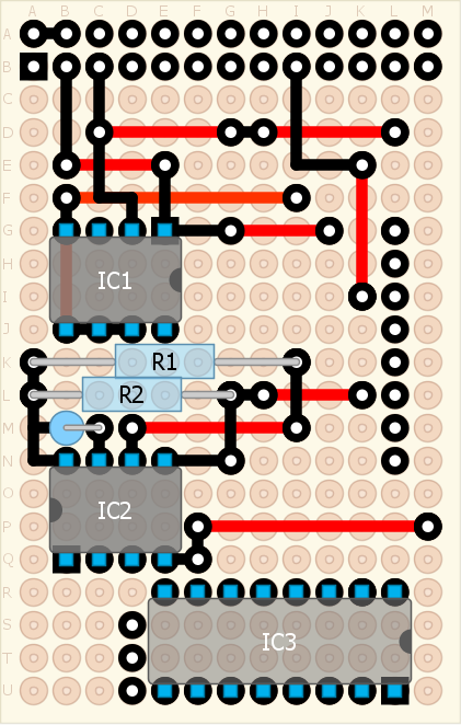
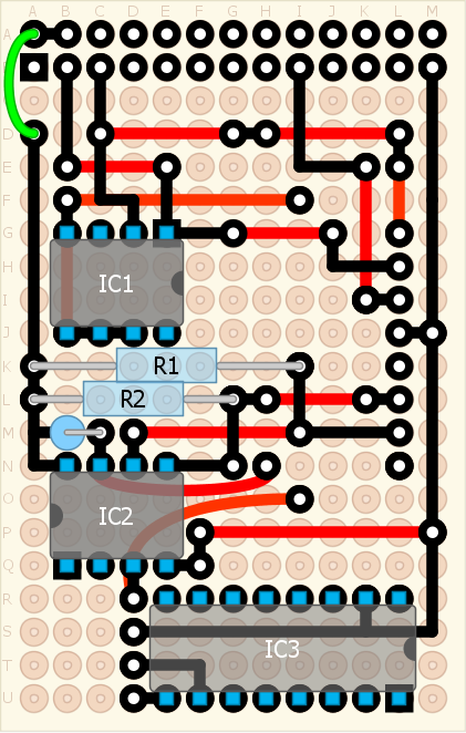
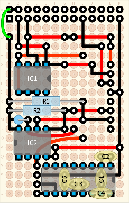
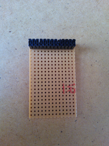
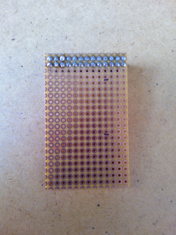
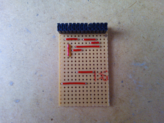
These are the steps required to build the extension board using a piece of perfboard.

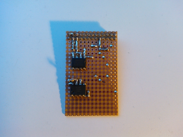
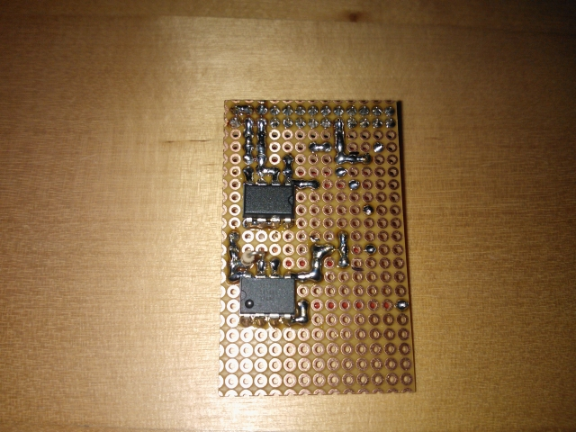
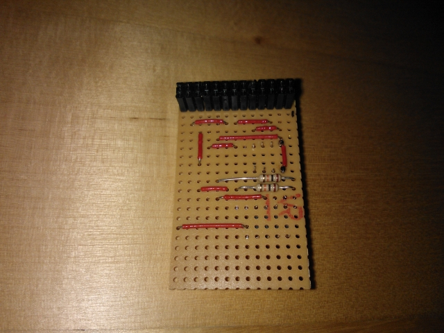
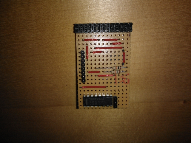
Some pictures of the real world board during build.
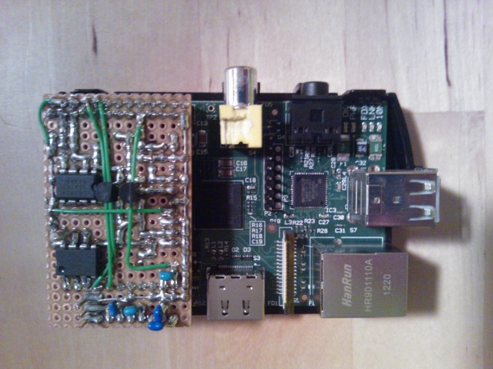
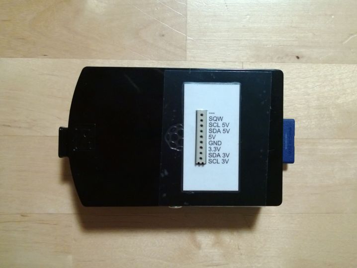
And this is how the extension board looks when mounted onto the raspberry. You can even provide access to the extension port by providing a cutout in the case.
Tools
This project shows how electronics projects can be done without too much costs and without the need of complex, expensive tools. In fact it was all done with freeware tools.
The schematic was drawn using TinyCad which is very easy to use to quickly sketch schematic drawings.
The production of the board itself was not that easy at first. Sure you can start with a sheet of paper and a pencil to design the perfboard but sooner or later you will come to the point where it is too cumbersome especially when modifying your layout. For professional PCB’s there are a lot of good, free, high quality tools available like Eagle or Target. But none of them is suitable for designing perfboard prototypes.
Fortunately, after some searching on the internet you will find some free tools for designing perfboards.
These are the tools. The Raspberry Pi extension was done using DIY Layout Creator (DIYLC in short).