Controlling your R/C transmitter from a PC using an Arduino
Sunday, July 21, 2013
Based on this post which describes controlling a Flight Simulator software with your R/C transmitter the following post describes the other way round: controlling a R/C model from the PC using an Arduino UNO.
The R/C transmitter used in this project is a Walkera Devention DEVO-7.
There are two ways to control a R/C modell from the PC:
- Using a standard R/C transmitter by using the trainer port most transmitters have (this should also work on older transmitter models). In this case the PC is responsible for providing a PPM signal which contains information’s about all transmitter channels. The PC can produce such a signal using it’s sound card or by using an Arduino connected to the PC via USB.
- By using only the transmitter module which could be found especially in newer 2GHz transmitters. The transmitter module used by the Devo7 is a WK-21201RF which uses a Cypress CYRF6936 wireless USB chip. This module has just 8 pins using standard signals like MISO, MOSI, Reset, CS, VDD, GND (Pinout can be found on Google) and can be directly connected to the Arduino.
This solution uses the DSC trainer port of the Devo7 (so there is no need to open the Devo7) and an Arduino for creating the PPM signal.
Description of the Trainer Mode
Training settings are described in the Devo7 user manual section 9. Trainig function.
Ensure that your transmitter is setup correctly otherwise the described solution may not work.
Normal trainer mode on the Devo7 is selected by the following procedure:
- Turn off trainers and trainees Devo7. Ensure no trainer cable is connected on both transmitters.
- Connect trainer cord to trainees Devo7.
- Turn on trainees Devo7.
After power up Devo7 checks for a valid PPM pulse train on the DSC port. If there is none it starts sending a PPM pulse train on the trainer cable and enters trainee mode. Also the transmitter is turned off. So there is no RF output from trainees transmitter. The display shows the link indicator PC%.
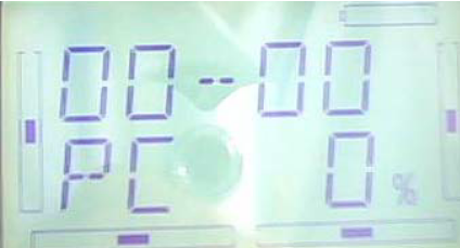
- Connect other side of trainer cable to trainers Devo7 DSC port.
- Turn on trainers Devo7.
As soon as the Devo7 sees a valid pulse train (from trainees Devo7) on the DSC port
after power up it enters trainer mode. Trainer binds to model the same way as if not
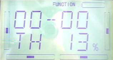
in trainer mode. Trainers transmitter outputs RF and display shows the normal TH% value.
Now the trainer can controll the model. Trainees actions are ignored.
- If Trainer pulls and holds the TRN switch trainers Devo7 in fact sends PPM signal from
trainees transmitter. Also trainers display shows actual TH% value from trainees Devo7.
- If trainer releases TRN switch trainees commands are ignored and trainer controls the
model again.
Hardware
You can use a standard audio cable with 3,5mm mono plugs as trainer cable. Ensure that you use mono plugs. If you use a stereo cable you have to connect the second ring to ground (3rd ring). The Devo7 checks the DSC port after power up if the second ring is grounded and if so enters trainer/trainee mode. If the Devo7 sees that the second ring is not grounded it enters firmware mode. For this you will need a UP02 adaptor.
To control your model from the PC we will use this procedure. So the PC becomes the trainee and the Devo7 must be kept in in trainee control mode by always enabling TRN switch.
The Arduino is connected to the PC and the PC can send control commands to the Arduino. The Arduino transforms these commands into a valid PPM pulse train which is then sent through D4 of the Arduino board to the Devo7.
Port D13 is PTT (push to transmit) an could be used to control the trainer switch using a relay or transistor. Normally the trainer switch must be hold by the trainer as long as he grants the trainee control over the model. So you can either change the pull switch with a normal switch or use D13 and the FirmataRC SetPTT command to control the switch with a relay.
Wire your R/C transmitter, the Arduino and the PC according the following schematic.
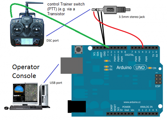
Arduino must be running before powering up the Devo7.
The FirmataRC protocol
The protocol is a very simple binary, frame based protocol. It is designed as an extension to the Firmata protocol. For a good description of outgoing and incoming Firmata messages have a look at here and here.
Some Firmata System Extensions (Sysex) are defined to control a R/C transmitter:
// Set configuration (0x50)
Send:
0xF0               Start Sysex
0x50               Configure transmitter
Channels           Number of transmitter channels 7-bits
Minpulse           minimum pulse length (ms) LSB 7-bits
Minpulse           minimum pulse length (ms) MSB 7-bits
Maxpulse           maximum pulse length (ms) LSB 7-bits
Maxpulse           maximum pulse length (ms) MSB 7-bits
Frame len          PPM frame length (ms) LSB 7-bits
Frame len          PPM frame length (ms) 7-bits
Frame len          PPM frame length (ms) 7-bits
Frame len          PPM frame length (ms) MSB 7-bits
0xF7               End Sysex
Receive:
0xF0               Start Sysex
0x50               Configure transmitter
Result             0x00 = OK, everything else = error 7-bits
0xF7               End Sysex


// Read configuration (0x51)
Send:
0xF0               Start Sysex
0x51               Read transmitter configuration
0xF7               End Sysex
Receive:
0xF0               Start Sysex
0x51               Read transmitter configuration
Result             0x00 = OK, everything else = error 7-bits
--- if Result == OK packet contains following fields ---
Channels           Number of transmitter channels 7-bits
Minpulse           minimum pulse length (ms) LSB 7-bits
Minpulse           minimum pulse length (ms) MSB 7-bits
Maxpulse           maximum pulse length (ms) LSB 7-bits
Maxpulse           maximum pulse length (ms) MSB 7-bits
Frame len          PPM frame length (ms) LSB 7-bits
Frame len          PPM frame length (ms) 7-bits
Frame len          PPM frame length (ms) 7-bits
Frame len          PPM frame length (ms) MSB 7-bits
--- packet always ends with 0xF7 regardless of status ---
0xF7               End Sysex


// Set channel value (0x52)
Send:
0xF0               Start Sysex
0x52               Set channel value
Channel            Channel number (0-127) 7-bits
Value              Channel value LSB 7-bits
Value              Channel value MSB 7-bits
0xF7               End Sysex
Receive:
0xF0               Start Sysex
0x52               Set channel value
Result             0x00 = OK, everything else = error 7-bits
Channel            Channel number (0-127) 7-bits
0xF7               End Sysex


// Read channel value (0x53)
Send:
0xF0               Start Sysex
0x53               Read channel value
Channel            Channel number (0-127) 7-bits
0xF7               End Sysex
Receive:
0xF0               Start Sysex
0x53               Read channel value
Result             0x00 = OK, everything else = error 7-bits
Channel            Channel number (0-127) 7-bits
--- if Result == OK packet contains following fields ---
Value              Channel value LSB 7-bits
Value              Channel value MSB 7-bits
--- packet always ends with 0xF7 regardless of status ---
0xF7               End Sysex


// Read all channel values (0x54)
Send:
0xF0               Start Sysex
0x54               Read all channel values
0xF7               End Sysex
Receive:
0xF0               Start Sysex
0x54               Read all channel values
Result             0x00 = OK, everything else = error 7-bits
--- if Result == OK packet contains following fields ---
Channels           Number of transmitter channels 7-bits
Channel-0          Current value for channel number 0 LSB 7-bits
Channel-0          Current value for channel number 0 MSB 7-bits
   :
Channel-N          Current value for channel number N LSB 7-bits
Channel-N          Current value for channel number N MSB 7-bits
--- packet always ends with 0xF7 regardless of status ---
0xF7               End Sysex


// Set PTT (Push To Transmit) (0x55)
Send:
0xF0               Start Sysex
0x55               Set PTT
PTT                PTT value, 0 = PTT low; > 0 PTT high; 7-bits
0xF7               End Sysex
Receive:
0xF0               Start Sysex
0x55               Set PTT
Result             0x00 = OK, everything else = error 7-bits
--- if Result == OK packet contains following fields ---
PTT                PTT value, 0 = PTT low; > 0 PTT high; 7-bits
--- packet always ends with 0xF7 regardless of status ---
0xF7               End Sysex


// Reset (0x5F)
Send:
0xF0               Start Sysex
0x5F               Reset all settings (config and chanels) to default value
0xF7               End Sysex
Receive:
0xF0               Start Sysex
0x5F               Reset all settings (config and chanels) to default value
Result             0x00 = OK, everything else = error 7-bits
0xF7               End Sysex
PC control software
To control the transmitter from the PC there is a little Windows utility (RcControl) which sends FirmataRC commands to the Arduino. It is written in C# and extends the SharpDuino library with the described Sysex Firmata extensions.
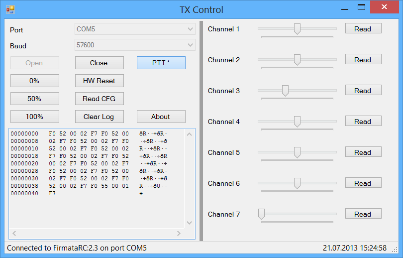
You can download the Arduino sketch and the PC utility here.
Another way
Just for completeness I provide here some pictures of the Devo7 transmitter module which would be the other way to control a R/C model from the PC.
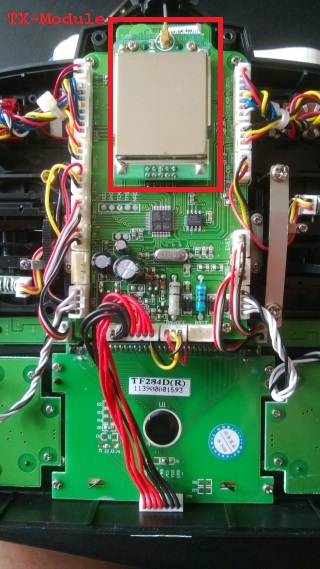
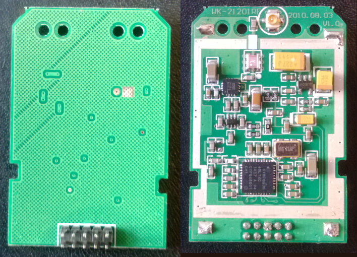
You can find more informations by googling either for the TX module name (WK-21201RF) or for the used chip name (CYRF6936 ).
