RX2635H using the ITG-3205 mems gyro
Sunday, April 12, 2015
 One of the important parts of a quadcopter controller is a gyro. The RX2635H uses an ITG-3205 from INVENSENSE. Accessing it is very simple as it uses the I2C interface (Two Wire Interface - TWI on the XMEGA) to read the X, Y and Z values of the gyro.
This post is part of a series
- Flashing new Firmware to Walkera RX/TX without UP02
- Decrypting receiver firmware
- Walkera receiver components
- Hello World firmware for the RX2635H board
- Serial port and external 16MHz oscillator
- Using the ITG-3205 mems gyro (this post)
- Walkera UP02 software clone: UP42
- Walkera RX2635H as generic development board?
- Walkera USB port
- Walkera + Arduino = Walkino
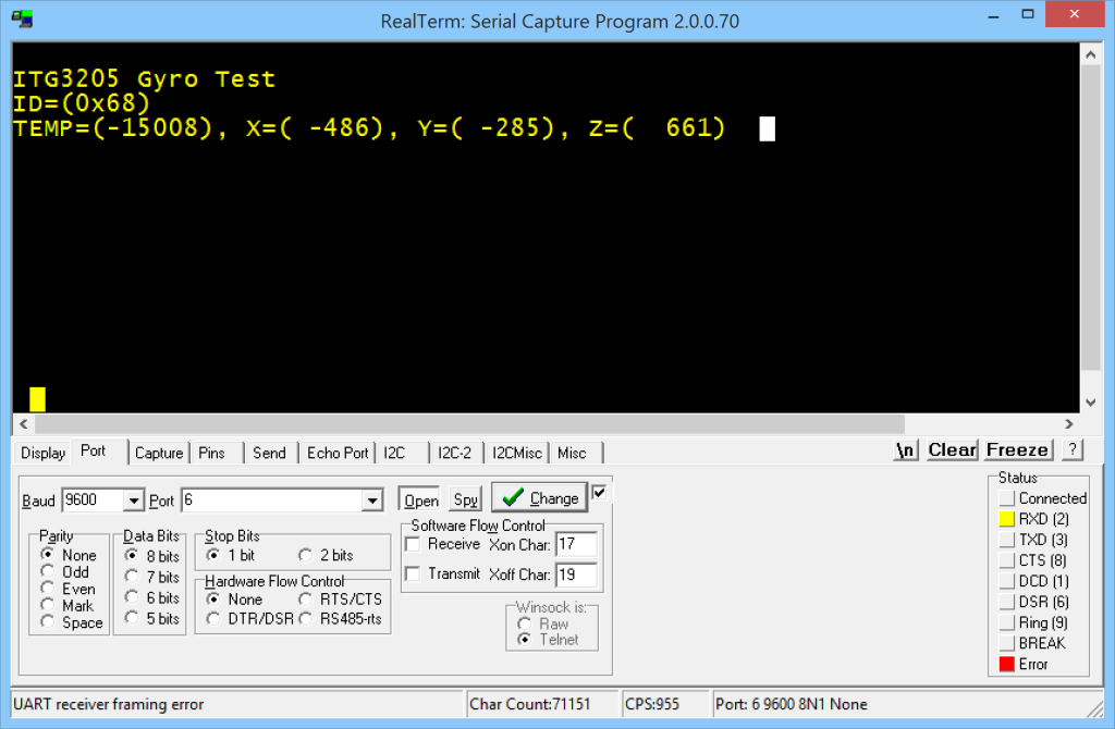
The ITG-3205 is connected to the XMEGA I2C (TWI) pins on PORTE. The following sample application reads the chip ID and the X, Y and Z values via I2C and prints it on the serial console. The ITG3-205 can have the 7bit I2C addresses 0×68 or 0×69 depending on pin 9. On the RX2635H board this pin is low (0) so it uses the I2C address 0×68.
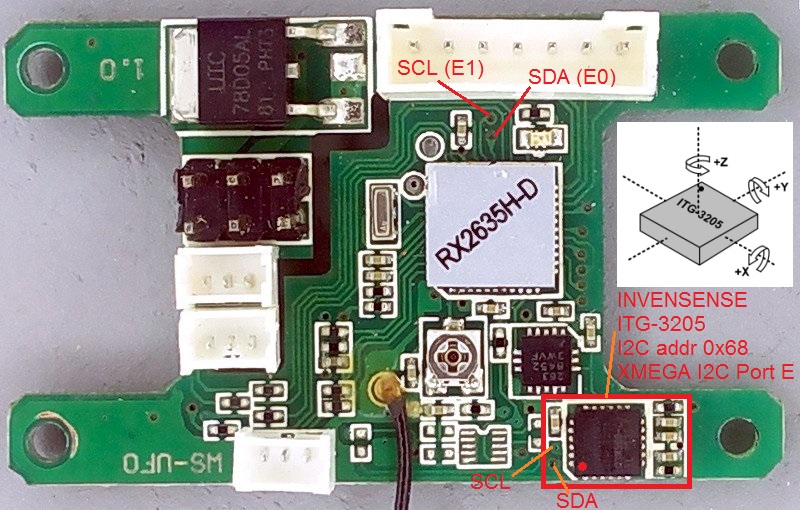
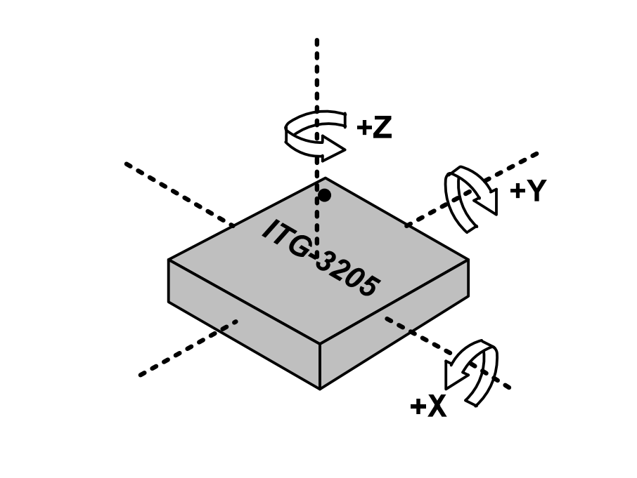
The RX2635H board image shows the location of the ITG-3205 and also its X, Y and Z sensitivity directions as well as the I2C data (SDA) and clock (SCL) lines.
Be sure to include a printf library (e.g. printf_min) in your project as it uses the printf C library function for output of the sensor values. You can download the complete AVR Studio solution here.
#include <avr/io.h>
#include <string.h>
#include <stdio.h>
// 16MHz CPU speed using external oscillator
#define F_CPU 16000000UL
char b = 1;
// Some defines and macros for calculating the I2C bus speed
// We use 100kHz for the I2C bus on XMEGA port E
#define I2C_E_BAUDRATE			100000
#define I2C_BAUD(F_SYS, F_TWI)	((F_SYS / (2 * F_TWI)) - 5)
#define I2C_E_BAUD				I2C_BAUD(F_CPU, I2C_E_BAUDRATE)
// ITG-3205 can have the 7bit I2C addresses 0x68 or 0x69 depending on
// ITG-3205 pin 9. On the RX2635H board this pin is low (0) so it has
// the I2C address 0x68. The address 0x68 is shifted 1 bit to the
// left because of the I2C read/write bit which gives 0xD0.
#define ITG3205_ADDR			0xD0
// buffer for reading and writing data on the I2C bus
uint8_t buffer[8];

// --------------------------------------------------------------------
// 16MHz external resonator setup
void setupOsc(void)
{
	//16MHz external crystal
	OSC_XOSCCTRL = OSC_FRQRANGE_12TO16_gc | OSC_XOSCSEL_XTAL_16KCLK_gc;

	//Enable external oscillator
	OSC_CTRL |= OSC_XOSCEN_bm;

	//Wait for clock stabilization
	while(!(OSC_STATUS & OSC_XOSCRDY_bm));

	// Selects clock system as external clock
	// through change protection mechanism
	CCP = CCP_IOREG_gc;
	CLK_CTRL = CLK_SCLKSEL_XOSC_gc;
}

// --------------------------------------------------------------------
// red LED on PD4
void setupLED(void)
{
	// PD4 = LED output
	PORTD_OUTSET = PIN4_bm;
	PORTD_DIRSET = PIN4_bm;
}
void LEDon(void)
{
	PORTD.OUTCLR = PIN4_bm;
}
void LEDoff(void)
{
	PORTD.OUTSET = PIN4_bm;
}

// --------------------------------------------------------------------
// 2nd serial port on PD6, PD7
void setupSerial(void)
{
	// PD7 = RS232 TX output
	PORTD_OUTSET = PIN7_bm;
	PORTD_DIRSET = PIN7_bm;

	// PD6 = RS232 RX input
	PORTD_OUTCLR = PIN6_bm;
	PORTD_DIRCLR = PIN6_bm;

	// calculate 9600 baud
	// BSEL = (16000000 / (2^0 * 16 * 9600) - 1 = 103,1666
	// BSCALE = 0
	// FBAUD = (16000000 / (2^0 * 16 * (103 + 1)) = 9615.384
	USARTD1_BAUDCTRLB = 0;
	USARTD1_BAUDCTRLA = 0x67; // 103

	// Disable interrupts, just for safety
	USARTD1_CTRLA = 0;

	// 8 data bits, no parity and 1 stop bit
	USARTD1_CTRLC = USART_CHSIZE_8BIT_gc;

	// enable receive and transmit
	USARTD1_CTRLB = USART_TXEN_bm | USART_RXEN_bm;
}
void sendChar(char c)
{
	while( !(USARTD1_STATUS & USART_DREIF_bm) );

	USARTD1_DATA = c;
}
static int sendCharStream(char c, FILE *stream)
{
	if(c == 'n')
		sendCharStream('r', stream);

	sendChar(c);

	return 0;
}
void sendString(const char *text)
{
	while(*text)
	sendChar(*text++);
}
char receiveChar(void)
{
	while( !(USARTD1_STATUS & USART_RXCIF_bm) );

	return USARTD1_DATA;
}
int receiveCharStream(FILE *stream)
{
	char c = receiveChar();

	if(c == 'r')
		c = 'n';

	// Send to console what has been received, so we can
	// see when typing
	sendCharStream(c, stream);

	return c;
}

// --------------------------------------------------------------------
// I2C interface on  PORTE - connected to ITG-3205 gyro
void setupI2C_E()
{
	TWIE.MASTER.CTRLB = TWI_MASTER_SMEN_bm;
	TWIE.MASTER.BAUD = I2C_E_BAUD;
	TWIE.MASTER.CTRLA = TWI_MASTER_ENABLE_bm;
	TWIE.MASTER.STATUS = TWI_MASTER_BUSSTATE_IDLE_gc;
}
void writeI2C_E(uint8_t slaveAddr,
		uint8_t addr, uint8_t *buffer, uint8_t len)
{
	TWIE.MASTER.ADDR = slaveAddr;
	while( !(TWIE.MASTER.STATUS & TWI_MASTER_WIF_bm) );

	TWIE.MASTER.DATA = addr;
	while( !(TWIE.MASTER.STATUS & TWI_MASTER_WIF_bm) );

	for(uint8_t i = 0; i < len; i++)
	{
		TWIE.MASTER.DATA = buffer[i];
		while( !(TWIE.MASTER.STATUS & TWI_MASTER_WIF_bm) );
	}

	TWIE.MASTER.CTRLC = TWI_MASTER_CMD_STOP_gc;
}
void readI2C_E(uint8_t slaveAddr,
		uint8_t addr, uint8_t *buffer, uint8_t len)
{
	uint8_t slaveReadAddr = slaveAddr | 0x01;

	TWIE.MASTER.ADDR = slaveAddr;
	while( !(TWIE.MASTER.STATUS & TWI_MASTER_WIF_bm) );
	TWIE.MASTER.DATA = addr;
	while( !(TWIE.MASTER.STATUS & TWI_MASTER_WIF_bm) );

	TWIE.MASTER.ADDR = slaveReadAddr;

	for(uint8_t i = 0; i < len; i++)
	{
		while( !(TWIE.MASTER.STATUS & TWI_MASTER_RIF_bm) );

		if((i + 1) == len)
			TWIE.MASTER.CTRLC |= TWI_MASTER_ACKACT_bm;
		else
			TWIE.MASTER.CTRLC &= ~TWI_MASTER_ACKACT_bm;

		buffer[i] = TWIE.MASTER.DATA;
	}
}

// --------------------------------------------------------------------
// main part
// use printf to print X,Y and Z values from the gyro to the
// serial port
FILE serialStream = FDEV_SETUP_STREAM(sendCharStream,
							receiveCharStream, _FDEV_SETUP_RW);
int main(void)
{
	int16_t T;
	int16_t X;
	int16_t Y;
	int16_t Z;

	setupOsc();
	setupLED();
	setupSerial();
	stdout = stdin = &serialStream;
	setupI2C_E();
	printf("\r\nITG-3205 Gyro Test\r\n");

	// read ID from gyro
	// see page 23 of ITG-3205 manual
	readI2C_E(ITG3205_ADDR, 0x00, buffer, 1);
	printf("ID=(0x%02x)\r\n", buffer[0]);

	while(1)
	{
		memset(&buffer, 0, sizeof(buffer));

		// read Temperature, X, Y and Z values from gyro
		// see page 27 of ITG-3205 manual
		readI2C_E(ITG3205_ADDR, 0x1B, buffer, 8);
		T = (buffer[0] << 8) + buffer[1];
		X = (buffer[2] << 8) + buffer[3];
		Y = (buffer[4] << 8) + buffer[5];
		Z = (buffer[6] << 8) + buffer[7];
		printf("TEMP=(%6d), X=(%6d), Y=(%6d), Z=(%6d)     \r",
			T, X, Y, Z);

		if(b) LEDon(); else LEDoff();
		b = !b;
	}
}