A Smart RS232 Server WatchDog  

Table of contents

Purpose

Who doesn't know the problem - without a server handling mails, hosting the own homepage and providing various other services nothin goes today. Lucky if you are hosting this server at a server hosting provider providing 24/7 support. In case of a problem just calling the helpdesk would (normally) be enough to bring the server back "on air". But what about if your server is located in your basement or even on the other side of the world and no one is at home or available on site to provide support? In most cases power cycling the server is enough to solve most problems and thats what this device is designed for. It monitors the server via a serial RS232 interface and if it fails, does a powercycle to restart the server.


DISCLAIMER

THIS SITE  INCLUDING ALL  ITS CONTENT  (TEXT, PICTURES,  BINARIES ETC.)  IS NOT
ALLOWED TO BE  USED IN CRIMINAL OR  ILLEGAL ACTIVITIES. IT IS FOR NON COMERCIAL
PURPOSE ONLY! I  AM IN NO WAY RESPONSIBLE FOR  ANY EXTERNAL CONTENT  POINTED TO
FROM THIS SITE.   UNDER  NO  CIRCUMSTANCES I  AM RESPONSIBLE  FOR  ANY  DAMAGES
TO YOUR RADIO, PC OR OTHER  EQUIPMENT. USE THIS  SITE  AND  ALL OF ITS  CONTENT
AT YOUR  OWN  RISK! BY USING  THIS  SITE  AND  ITS  CONTENT  YOU HAVE  ACCEPTED
THIS DISCLAIMER.

Features

The design itself is not revulotionary new but instead it's a classical microcontroller design consisting of a Microchip PIC16F819, a 4 MHz oscilliator, RS232 interface with a MAX232, 5V power supply based on 220V to 6V transformer, rectifier and 78L05 voltage regulator and a S202S12 solid state relay for switching 220V on or off. All these things are inside a chassis with 220V jack and port. Place it between the 220V server power source and the server, connect the WatchDog's serial port to a free serial port on the server and load the server software, which sends heart beats to the WatchDog, on the server and you are done. The solid state relay S202S12 is capable of switching 8A but to be on the save side the internal fuse of the WatchDog is only 5A. The WatchDog (despite of its name) can also be used as a RS232 controlled On/Off switch. Read more about in the Configuration section. To reduce space a RJ45 jack was used for the serial interface. The pinout is as follows (as seen from the plug):

PinDescription
1-
2TX
3RX
4DTR
5GND
6-
7RTS
8-

Schematics


WatchDog schematic

The PCB

The PCB for the WatchDog is single sided with only one bridge (above C9) so it's quite simple to fabricate. No SMD parts are used thus it's easy to build. Under IC1 are two solder jumpers to select which RS232 control line should be used as physical heartbeat. Either DTR or RTS can be selected by soldering the corresponding pads.

 
Componen placement   PCB full view
 
 
Various views of the finished WatchDog
 
The WatchDog internals

You can download a PDF File with the schematic and the PCB here and the firmware HEX file here.
If you dont have the Adobe Acrobat Reader installed on your machine you can find it here

Usage

To tell the WatchDog what to do you must configure it first. The Firmware uses realistic default values but in most cases you have to alter these to suit your needs. Connect the WatchDog to a PC's serial port and start Hyperterm (on Unix use Minicom). The WatchDog starts with a one second delay to wait til power is stable. After that it outputs a single '+' (plus character) on the serial port and waits for 5 seconds for an input. If it receives a '-' (minus character) during this period it enters config mode. If it receives a '*' (star character) parameters are reset to default values before entering config mode. All other characters received during this 5 seconds stop this period and continue with normal operation. The same happens if no character is received.


 WatchDog V1.0, 26.8.2007, See also http://www.min.at/prinz/oe1rib/watchdog 
 ESC) Cancel, ENTER) Save, Press Character before colon to change value

 Flags:
 --------------------------------
 a: On/Off mode: N
 b: WatchDog mode: Y
 c: OK with every Character: N
 d: OK by level change on Pin: N
 e: Show prompt: Y
 f: Show LED status: Y
 g: Start with output power on: Y

 Values:
 --------------------------------
 h: Start Delay (seconds): 120
 i: Prompt Character: >
 j: OK Character: o
 k: ON Character: 1
 l: OFF Character: 0
 m: Timeout (seconds): 030
 n: Grace period (count): 004
WatchDog configuration displaying the default values

To change a configuration parameter press the character before the ':' (colon). If this parameter is a flag it just toggles its value and the configuration overview is displayed again. In case of a character or a numeric value you will see a prompt where you can change the value.

                                                                            
 i: Press Character: 

To change a character just press the character at the "press character" prompt. Escape cancels the input and could not be used as input.

                                                                            
 m: Enter Value:

At this prompt you can enter a numeric value in the range 000 - 999. Enter accepts the value, escape cancels the input, backspace can be used to correct the value.

A description of the parameter follows:
Character Parameter Description
a On/Off mode Allows turning output power on and off by sending a ON or OFF character to the WatchDog. If WatchDog mode is set to YES the on or off state must be acknowledged within [TimeOut] by using the ON, OFF, OK characters or if OK with every Character is set to YES with any character.
b WatchDog mode Enables the [TimeOut] and [Grace] parameters. WatchDog must be triggerd by either the OK character, any character (if OK with every Character is set to YES or by the ON or OFF character if On/Off mode is set to YES.
c OK with every Character Allows triggering or acknowledgement of power output by any character sent to the WatchDog
d OK by level change on Pin The WatchDog can also be triggered or acknowledged by a level change on either the DTR or RTS line of the RS232. To configure which signal should be used a jumper must be soldered on the PCB.
e Show prompt Display Prompt Character every time the WatchDog is triggered, a [Grace] period ends or a power cycle occures.
f Show LED status Include the current LED status in the prompt in the form of !#[Prompt Character]. So if promt is set to > and [Grace] = 3 the output would be !3>
g Start with output power on If set to YES output power is on if the WatchDog is plugged into a 220V Socket
h Start Delay (seconds) After pluggin the WatchDog into a 220V socket wait this much seconds. This parameter also specifies the duration of the power cycle (how many seconds output power should be turned off)
i Prompt Character Which character to use as prompt. See also Show prompt parameter
j OK Character Which character should be used as OK from the server.
k ON Character The character to be used to turn output power on
l OFF Character The character to be used to turn output power off
m Timeout (seconds) How many seconds to wait for a WatchDog trigger
n Grace period (count) How many times Timeout can go by without a WatchDog trigger.
When you are finished configuring the WatchDog press enter to save the settings or press escape to discard all current changes. After enter or escape the WatchDog resets and starts like it was plugged into a 220V socket.

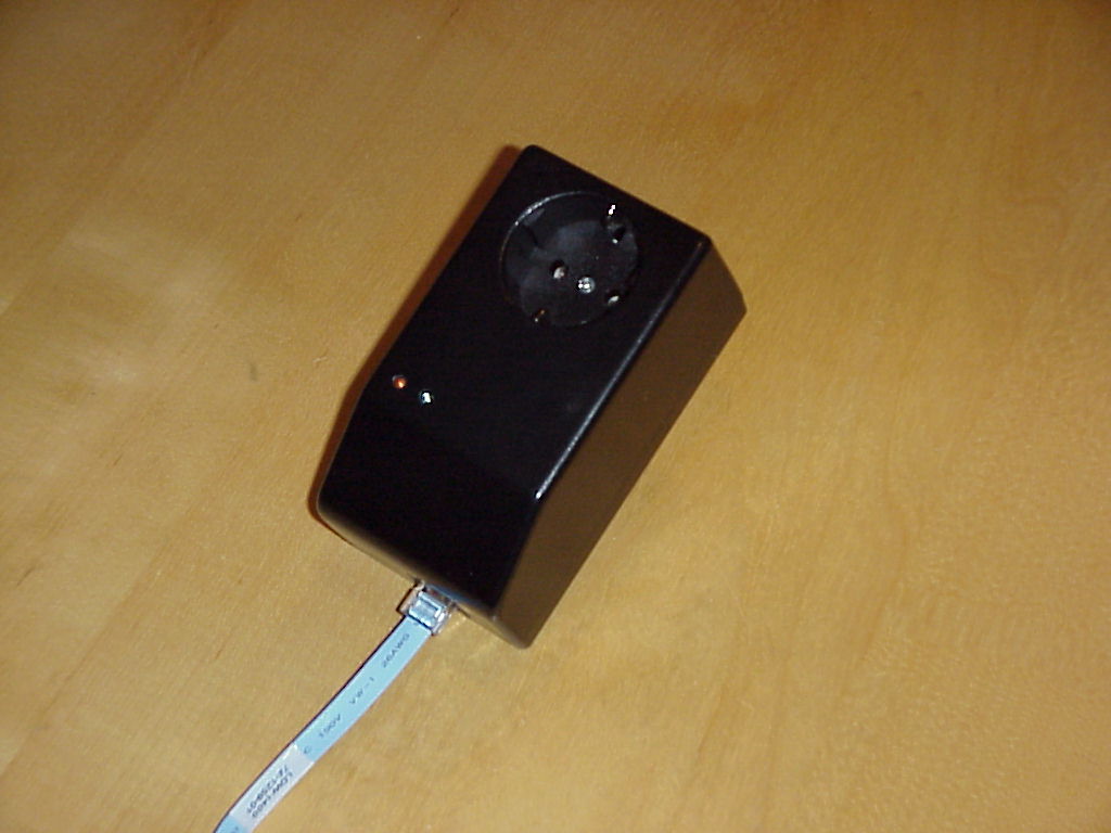
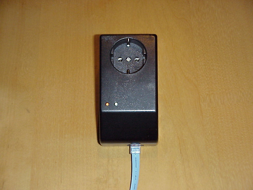
The WatchDog uses 2 LED's to show it's status. A red LED indicates 220V output power and a green LED shows the current WatchDog status.

Status LED's Description
Red LED off, green LED off: In normal operation output power turned off using OFF character or no 220V input power.
Red LED steady, green LED off: Normal operation, WatchDog is receiving heartbeats or in On/Off mode set to YES and WD mode turned off output power turned on by using ON Character.
Red LED steady, green LED blinking every second: No heartbeat received for [TimeOut] seconds, [Grace] is >= 3, output power supplyed.
Red LED steady, green LED blinking every 500ms (1/2 second): No heartbeat received for [TimeOut] seconds, [Grace] is = 2, output power supplyed.
Red LED steady, green LED blinking every 200ms (1/5 second): No heartbeat received for [TimeOut] seconds, [Grace] is = 1, output power supplyed.
WatchDog performing a power cycle, WatchDog has not received a heartbeat for [Timeout] * [Grace] seconds, no output power supplyed

WatchDog status LED's

Notes & Comments

The firmware of the system is written entirely in assembler code and uses about the half of the used PIC 16F819. So there is enough room for improvements

in the Press

This paper can also be found in the german HAM Radio Magazine
"Funkamateur" at www.funkamateur.de, Issue 01 / 2008, Page 32,
Title: "Automatischer Rechnerneustart mittels Watchdog"

Credits

If you have any comments or sugestions just drop me a line.

73, OE1RIB