Yaesu FT-817 / FT-100 CAT Interface Cable
(Y-Cable)
Table of contents
Purpose
The intentions to start this project where the following points:
- I was not willing to pay a lot of money for the original Yeasu CAT CT-62 cable
- I needed a cable which works with nearly every Software
- QRP means low power and small so the cable should also be a QRP cable
(meaning super small dimensions and different types of power sources)
And that's the result. A CAT cable with RS232 level shifter fitted inside a normal DB9 RS232 plug
housing capable of using either DTR or RTS for PTT control and also capable of beeing powered by
the PC or the Radio.
DISCLAIMER:
THIS CABLE IS JUST ONE WAY TO CONNECT YOUR RADIO TO A PC - OTHER, MAY BE BETTER WAYS,
MAY EXISTS - IT'S UP TO YOUR RESPONSIBILITY IF YOU BUILD AND USE THIS CABLE. UNDER NO
CIRCUMSTANCES I AM RESPONSIBLE  FOR ANY DAMAGES TO YOUR RADIO OR PC! THIS  DEVICE WAS
TESTED  WITH  DIFFERENT  RADIOS AND PC'S AND  UNTIL  NOW IT  WORKS WITHOUT  PROBLEMS.
Schematics
The whole project consists of two schematics. The CAT-Interface with the RS232 level converter and
the PTT driver, and the SoundCard-Interface connecting the computers Soundcard to the radio.
The CAT-Interface is responsible of converting the original PC RS232 voltage levels of about 12V
to the Radio level of 5V. To do this it needs a power source. This could either be the 13.8V source
on the ACC Connector of the Radio or the RTS/DTR Pins of the Computers RS232 Port.
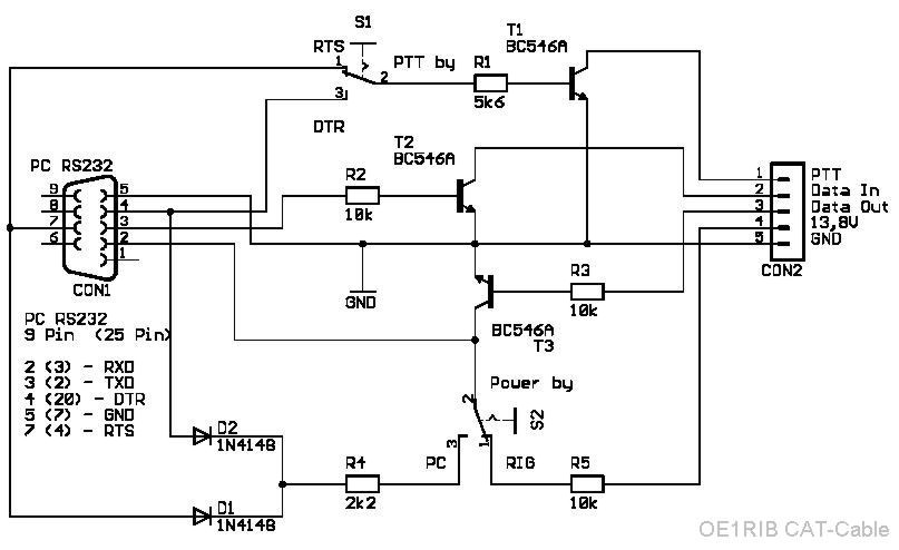
Image 1: CAT-Interface
Because of the fact that the PTT pin on the FT-817/FT-100 is located on the Data Connector and not
on the ACC jack and that it should be possible to use the CAT Cable without the Soundcard
Interface a hybrid Cable was invented. As you can see on the Drawing below the complete Cable
consists of two completely independend Cables each capable of working without the other.
One cable handles the CAT communication and PTT handling (the Y-Cable) and the other one
handles the NF from and to the Radio.
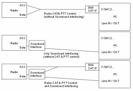
Image 2: Cable overview
The PCB
Dont be afraid about the fact that this Cable is completely built using SMD components. It just looks
complicated but it isn't. You only have to be carefull when producing the PCB. There are fairly small
copper traces on it. If you do it wrong they can be etched away.
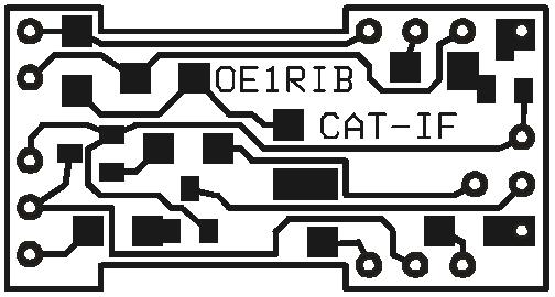
Image 3: The Printed Circuit Board CAT Interface
To find the components from the Schematic you can use the Silkscreen. The Resistor R* (red marked in
the Silkscreen) is not shown in the Schematic drawing. It isn't actualy a resistor at all it is a
0 Ohm resistor just working as a "bridge" between two points on the PCB. If you can't get one
you can use a very short piece of wire.
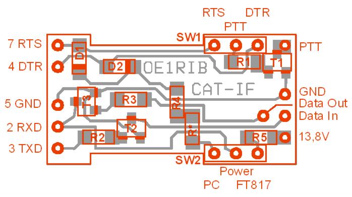
Image 4: Component positions CAT Interface
You can download a PDF File with the schematic and the PCB here.
If you
dont have the Adobe Acrobat Reader installed on your machin you can find it here

Pictures of the finished Cable
Here you can see how the cable looks during different stages of the building process and how it
looks when it's finished. Be sure to get the right DP9 Housing so that the PCB fits. If you use
another DB9 housing you will have to trim the PCB accordingly.
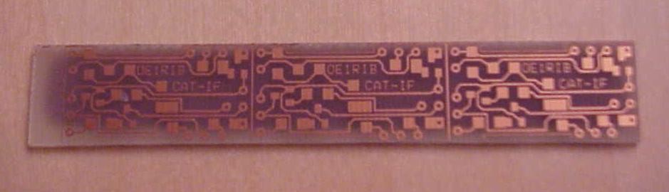
Image 5: Etched PCB for three Cables
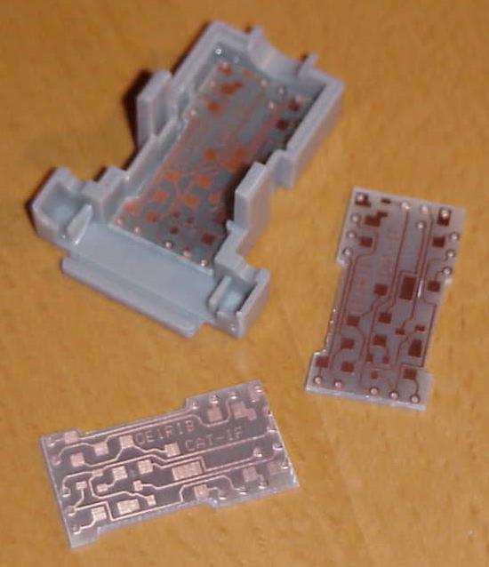
Image 6: Cutted and trimed PCB with Plug housing
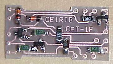
Image 7: PCB with SMD Components soldered
|
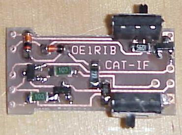
Image 8: SMD Switches in place
|
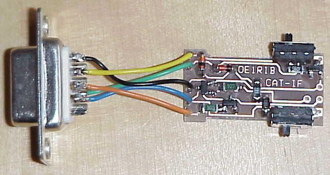
Image 9: DB9 Connector connected to PCB
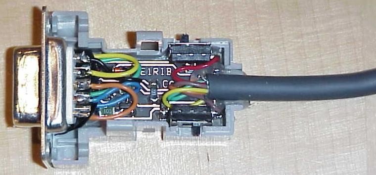
Image 10: Before closing the Plug housing
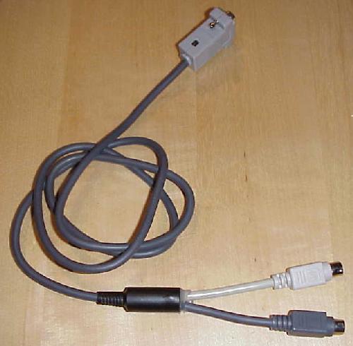
Image 11: The finished Y-Cable
Notes & Comments
Radios & Applications
The Cable was tested with the following Radios:
and Applications:
- HamScope V4
- FT-817 Commander
- DigiPan
If you have successfully tested it with other types of Radios just let me know so that i can
put a statement about it here on the page.
Power supply
Some notes to the power supply of the Cable. Power is either taken from the PC's RS232 Port or from
the Radio. To function properly in PC powered mode one of the RTS/DTR Pins has at least to be set high by the
Application. If you have an Application which doesn't set it correct you have to switch to Radio
powered mode. But be sure to either disconnect or switch back to PC powered mode when you finished
your work. Some Radios (like the FT-817) supply power to the Cable even if they are turned Off.
This is not a big problem when your Radio is in the Shak. But when you run on Batteries you could be
sure they are empty the next time you want to use your Radio. In PC powered mode you dont have to care about it
because when you switch off your PC the Cable is no longer powered. You have been warned!
Modifications
Sometimes the combined powerer scheme by DTR/RTS could be a problem. Not all software handles these
signals the way you want it. To overcome this it would be a good idea to use a 3 position switch for
S1 with off in middle position. Thus you can isolate PTT completely from the PC but you must then set
S2 to FT-817 powered mode.
Also if you use a 3 position 4 pin switch and a super small power jack you can power the interface from
either the PC, the FT-817 OR externaly using a battery or power supply. I have not done this in this
project because it is not trivial to find such small switches.
Additional Infos
- 2004-01-07
Just for reference: Here you will find the Pinout of the
ACC and DATA Ports of the FT-817 as seen from behind the radio (also shown in the FT-817
Manual). Connect the MiniCat Cable to the blue marked Pins.
| CAT-IF | ACC | Data |
| GND | GND | - |
| 13.8V | 13.8V | - |
| Data Out | TXD | - |
| Data In | RXD | - |
| PTT | - | PTT |
in the Press
 |
This paper can also be found in the german HAM Radio Magazine
"Funkamateur" at
www.funkamateur.de, Issue 10 / 2003, Page 1027,
Title: "Flexibles Subminiatur-CAT-Kabel für FT-817, FT-100 und andere" |
Credits
This Cable is based on some Infos found on the Internet from VE3CVG and DF8DL and modified by me
OE1RIB, Richard
If you have any comments or sugestions just drop me a line.
73, OE1RIB