Image 1: Schematic of the I2C-Interface
DISCLAIMER:
THIS CONTENT IS PROVIDED TO INTERESTED PEOPLE "AS IS" FOR NON COMERCIAL
PURPOSE ONLY. UNDER  NO CIRCUMSTANCES I AM RESPONSIBLE  FOR ANY DAMAGES
TO  YOUR RADIO, PC OR OTHER  EQUIPMENT. THIS  DEVICE  WAS TESTED  UNDER
DIFFERENT  CONDITIONS   AND  UNTIL  NOW  IT  WORKS   WITHOUT  PROBLEMS.
Standard RC servos are controlled using a simple PWM signal with a frequency of about 50Hz. The position of the servo is a result of the duty cycle of the signal. Left results from a 1ms, center from a 1,5ms and right from a 2ms pulse.
There are many different servos with varying position speeds and powers. Depending on your current needs you have to choose the right one. There are also lots of servo manufacturers with varying servo connectors. But this problem is easy to overcome. Every servo has a connector with 3 pins. Power+, power- and signal. Only the order of these pins differs. So all you have to do to use a servo with the I2C interface is to ensure that the pins are ordered like this: power-, power+ and signal. On cheap servo connectors you can just rearange the pins on better ones where this is not possible just cut off the old connector and solder a new one.
Heart of the interface is a Microchip PIC 16F819 microcontroller using a 20MHz crystal and just a few uncritical components. As the I2C bus is normaly used between components in the same circuit you have to use I2C extenders like the 82B715 to extend the bus up to e few meters. Jumper J1 allows you to power the servos either from the interface power or from another power source. The Jumpers A0-A2 allows the daisy chaining of up to 8 I2C interfaces givin a total of 64 servos you can control.
Despite a its simplicity this interface offers some interesing features:
The I2C Protocol
Commands to the I2C Servo Interface consists of 2 or 3 bytes depending on function.
The first byte represents the I2C address of the interface which should handle the request. The Address consists of 3 parts: a fixed part. A part which can be configured with the address jumpers A0-A2 and the mode bit which specifies the mode - read or write.
The command follows in byte number two. Bits 7-3 represents the command and bits 2-0 the servo. Commands which are valid for all servos ignore bits 2-0.
The third byte contains an optional value. Some commands need this - like for example the set servo position command. A value of 0 means left, 128 middle and 255 right servo position. In case of the set trimm command this means: values less than 128 (with cleared high bit) are added to the servo position value and values greater 128 (set high bit) are subtracted from the servo position moving the center position to the right. But be aware - some servos can be destroyed moving it beyond their limits!
| Set Commands | I2C_CMD_SetServoPosition | B'00000000' | Set's a servos position (0-left, 128 middle, 255-right) | I2C_CMD_SetServoTrim | B'00001000' | Set's a servos trimm value 0-127 moves center position to left, 128-255 moves to right. |
| Write Commands | ||
| I2C_CMD_Positions2EEPROM | B'00010000' | Saves all servo positions to internal EEPROM. |
| I2C_CMD_Trims2EEPROM | B'00011000' | Saves all servo timm values to the internal EEPROM. |
| I2C_CMD_WriteConfigByte | B'01000000' | Writes the config byte to the EEPROM |
| I2C_CMD_WriteOnOffMask | B'01101000' | Writes to On/Off bitmask to the EEPROM. Bit 7-0 each represents one servo of the interface. A set bit enables a servo, a cleared bit disables it. |
| Init Commands | ||
| I2C_CMD_InitAll | B'00100000' | Initializes all servo positions and trimms to center position. |
| I2C_CMD_LoadAllFromEEPROM | B'00101000' | Restores all servo positions and trimms to values previously stored in EEPROM. |
| I2C_CMD_AllPositions2Center | B'01010000' | Moves all servos to center position. |
| I2C_CMD_AllTrims2Center | B'01011000' | Resets all trimm values to center position. |
| Read Commands | ||
| I2C_CMD_ReadServoPosition | B'00110000' | Reads a given servos position. |
| I2C_CMD_ReadTrimPosition | B'00111000' | Reads a given servos trimm value. |
| I2C_CMD_ReadConfigByte | B'01001000' | Reads the current config value. |
| I2C_CMD_ReadOnOffMask | B'01100000' | Reads the current On/Off bitmask. |
The configbyte
By using the configbyte you can alter the behaviour of the interface after a reset. If bit POS is set all servos enter the previous saved positions from the EEPROM after a reset. The same applies if bit TRIM is set for the trimm values. ONOFF turn servos on or off after a reset depending on the saved on/off bitmask. Bit CFG is normaly set and signals a valid EEPROM configuration. If you clear this bit the EEPROM is filled with default values after a reset and this bit is then set again.
| 7 | 6 | 5 | 4 | 3 | 2 | 1 | 0 |
| CFG | - | - | - | - | ONOFF | POS | TRIM |
Example: reading the configbyte
For reading the configbyte you have to process to following steps.
| Address | Command/Servo | Data |
| 0011AAA0 | CCCCCSSS | BBBBBBBB |
| Adresse: | 0011 XXX 0 | 0011 | fixed part of the I2C address |
| AAA | Jumper A0-A2 for I2C address selection | ||
| 0 | Mode 0) write, 1) read | ||
| Command/Servo: | CCCCC SSS | CCCCC | Servo command (see I2C protocoll) |
| SSS | number of servo (0-7) | ||
| Daten: | BBBBBBBB | BBBBBBBB | optional data depending on command |
 Image 2: The PCB |
 Image 3: Component placement |
You can download a PDF File with the schematic and the PCB here.
If you dont have the Adobe Acrobat Reader installed on your machine you can find it here
![]()
The firmware for the microcontroller in MPLAB assembler can be found
here.
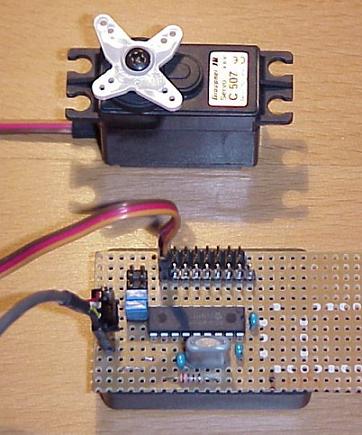
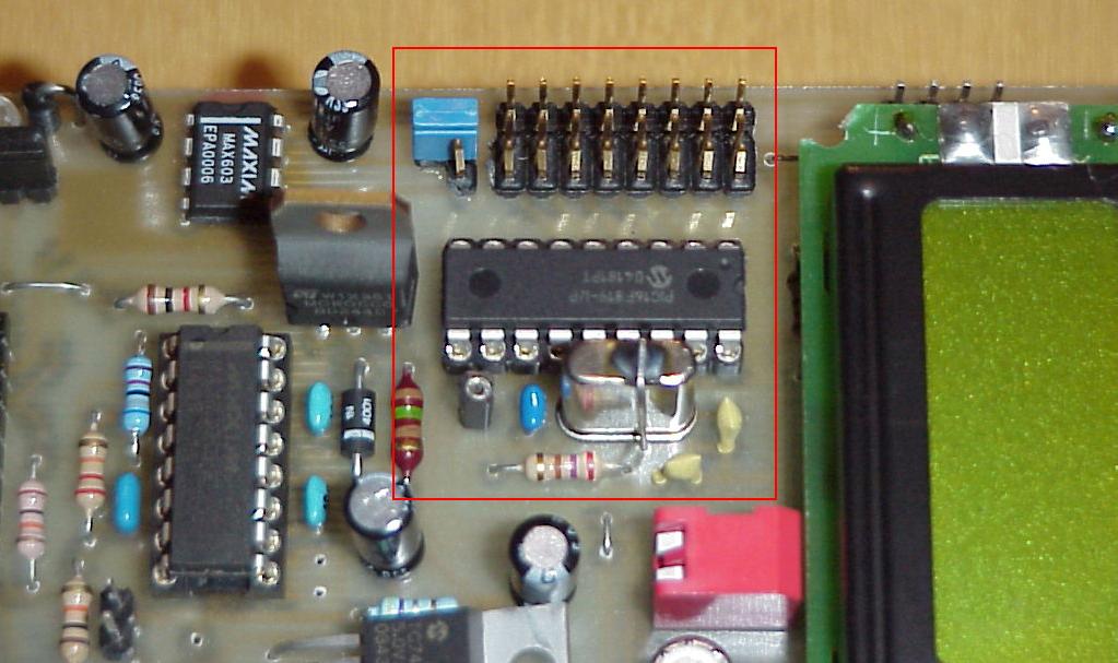
Image 5: Servo interface embedded on the IPS expansion board
 |
This paper can also be found in the german HAM Radio Magazine
"Funkamateur" at www.funkamateur.de, Issue 04 / 2005, Page 366, Title: "Bewegung einmal anders" |
73, OE1RIB