StickLock
Wednesday, June 5, 2019
Using a YubiKey (or other USB security token) to unlock physical things.
While researching locks and lockable storage for a new premise I found lots of LockPicking information about how to hack and break into products from even renowned companies. It’s not only a waste of money buying “high security” products which could be unlocked by just a paper clip like shown in this Video but might also be dangerous.
At the same time I use my YubiKey daily with IT systems and services. So I thought to myself:
“Why not use a YubiKey as a key for physical storage/property?”.
So I started another research, if, how and with how much effort a lock for physical things could be designed which uses a standard USB security token as key.
Fortunately it was easy to design such a lock. The outcome is the “StickLock” (short “SL”) described in this project.
Note: Latest software could be found on GitHub.
Note: As some commenters pointed out StickLock might have more vulnerabilities then a normal, physical lock. This is only partially true and the section “Critics, comments and frequently asked questions” further down the page might help to put this blog post into the right context.
History
<2019-06-05> First version
<2019-08-15> Implemented new key type “Serial Number Only”
<2019-09-13> Notes on battery usage and low voltage monitor
Design
Goals
The design of the StickLock should meet the following goals:
- Easy to build
It should be possible to build StickLock in less then an hour even for non technicians.
- Cheap
No special, expensive, hard to get components.
- Verifiable
Open-Source, verifiable by anyone interested in the inner workings.
- Multiple key support
Support for at least three different USB security tokens.
- Multiple security
StickLock should support multiple security technologies e.g. static keys, HOTP (RFC-4226) etc.
- No complex user interface
Only a blue, red and green LED and a button should be enough to operate StickLock.
- No need to be online
StickLock does not need any internet connectivity.
- Electricity autonomous
SL should be able to operate a long time from batteries.
The Prototype
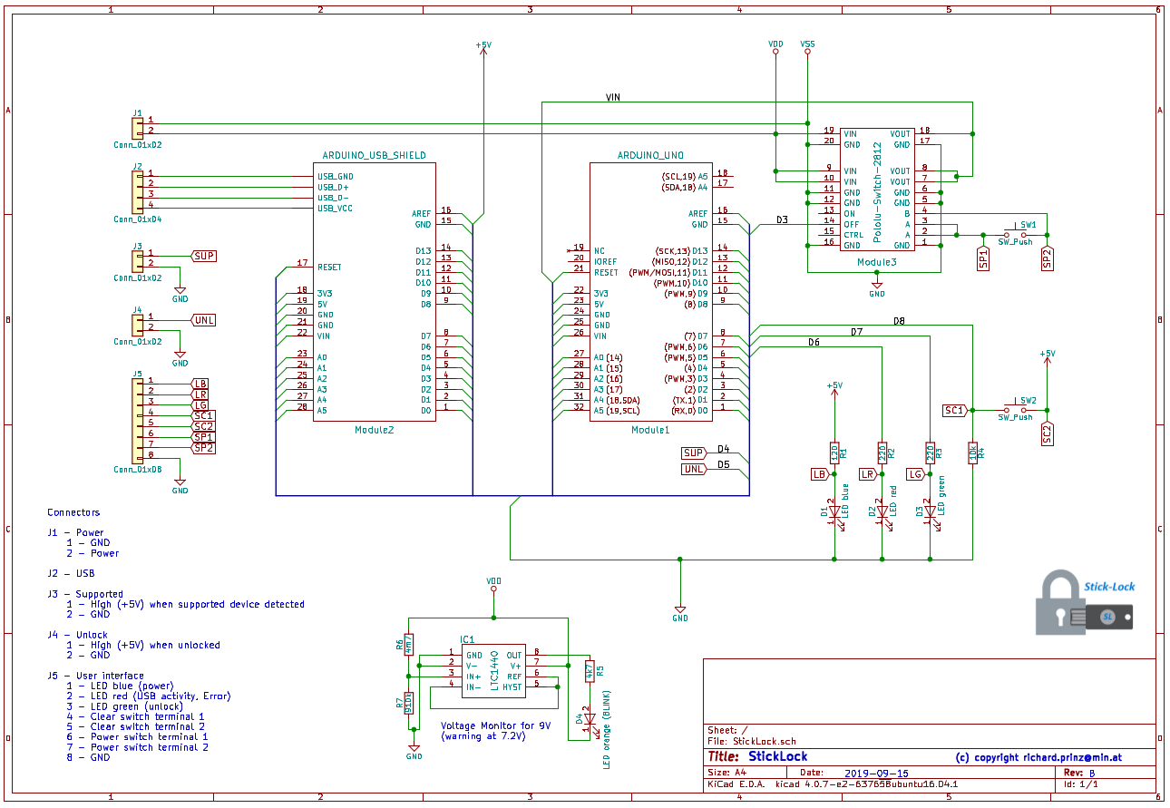
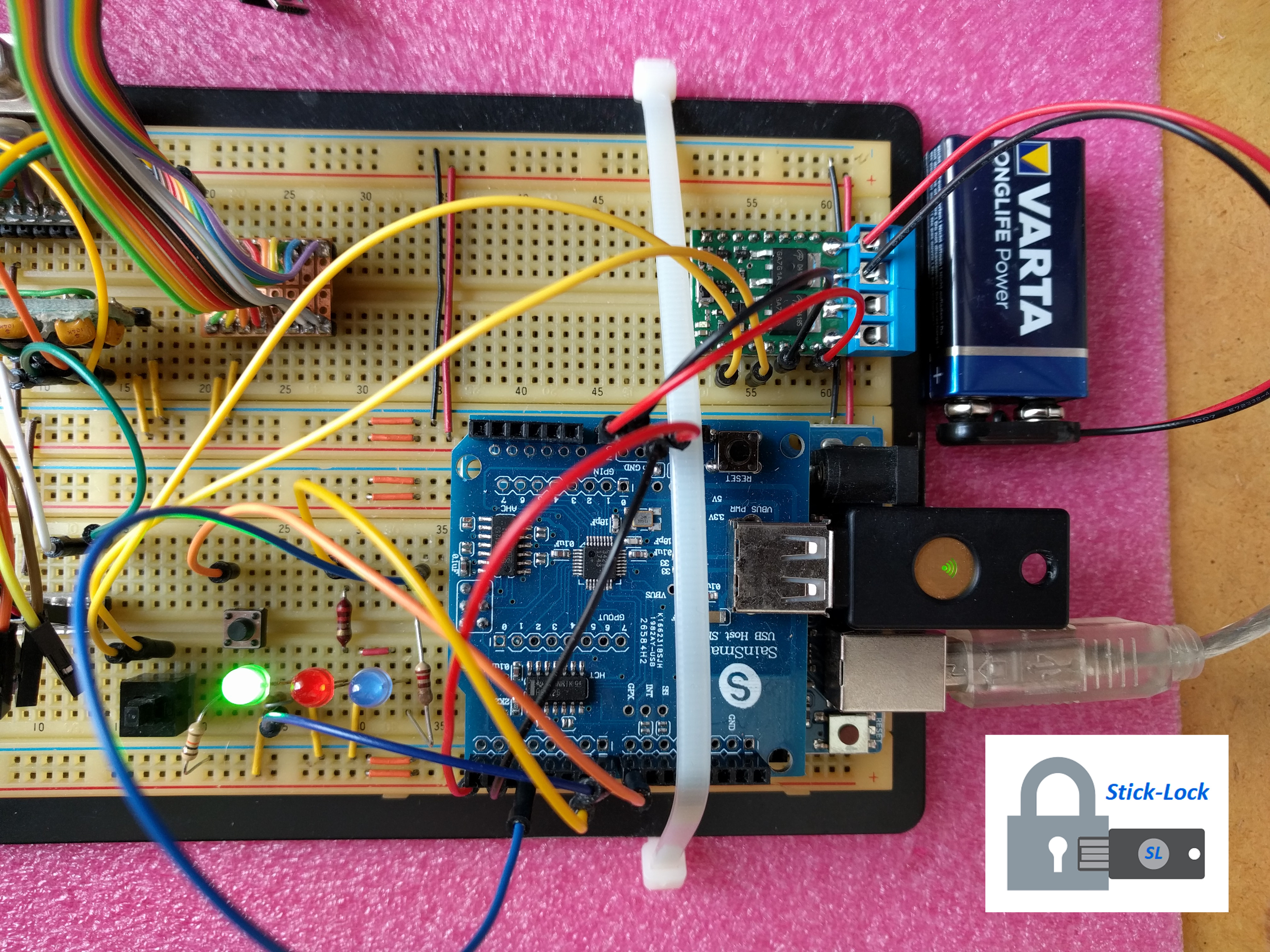
The prototype design uses cheap ready available components:
- a Arduino UNO (or compatible)
- a USB host shield or compatible based on the MAX3421E
- a Pololu Pushbutton Power Switch
- a USB Security Token with HOTP and/or HID Keyboard (not FIDO HID!) support like a YubiKey NEO, 4 or 5.
- some passive components like LED’s, switches and resistors etc.
Total amount of all components is about 50.00 EUR.
The schematic shows that the StickLock is very easy to build.
When SL is used with batteries some sort of battery monitor is required. Included in this design is a simple monitor which warns (using an orange blink LED) when the 9V battery becomes low (~ < 7.3V).
The following measurements might help to select the another one for your use case:
| Component | Power |
|---|---|
| Simple Voltage Monitor | 4µA |
| Polollu Switch | 28µA |
| Arduino + USB Shield (standby, no device attached) | 56mA |
| Arduino + USB Shield (standby, YubiKey attached) | 80mA |
| Arduino + USB Shield (unlock with YubiKey) | 90mA |
So in idle standby mode, SL uses ~32µA. The unlock process using a YubiKey takes on average 10 seconds and draws ~90mA. With a simple standard 9V block (~600mA) lots of unlocking action can be performed for a long time (although a 9V block is not the preferred battery type but easily available and cheap).
Note: To not always change the battery when low, a better solution would be to use a rechargeable battery with additional charger circuit. This might be included in an updated design.
Usage
Configuration
Before using StickLock, valid devices and keys must be configured. In normal operation SL does not provide any user interface via serial console (expect when explicitly enabled for testing and debugging - NOT RECOMMENDED FOR NORMAL OPERATION). To configure SL first enable the config flag in file `global.h`. Then modify `config.h` to match your devices and keys (details below). Flash your Arduino and you will see a menu displayed via serial console providing the following options:
StickLock 1.0.0 configuration mode …
Usage:
h : shows this usage information
D : print configured devices
d : print EEPROM devices
K : print configured keys
k : print EEPROM keys
c : export devices & keys in EEPROM as C code
w : write configured devices and keys to EEPROM
X : erase EEPROM!!
E : show EEPROM hex dump
>
Supported Devices
As soon as an USB device is connected to SL its USB Vendor-ID (VID) and Product-ID (PID) are read. If SL is configured to only allow supported devices (DEFAULT ENABLED, HIGHLY RECOMMENDED) then these information is matched against SL configured device data. In case the connected device’s VID and PID don’t match, SL will stop to interact with it. This is indicated by a continuous blinking red LED until the device is disconnected from SL.
Supported devices are configured in `config.h` with their VID, PID and a short descriptive text like in the following example:
const PROGMEM char device1_name[] = ”YubiKey NEO NFC”;
const PROGMEM char device2_name[] = ”YubiKey 5 NFC”;
const Device_t config_devices[] PROGMEM = {
    // VID     PID     Description
    {  0×1050, 0×0116, device1_name },
    {  0×1050, 0×0407, device2_name }
};
NOTE: It is possible to disable the supported devices check completely. In this case all USB HID devices will be accepted by SL. This can be done by uncommenting the line:
// #define DISABLE_SUPPORTED_DEVICE_CHECKS
in file `global.h`. THIS IS NOT RECOMMENDED!
Keys
SL supports four different key types: HOTP-6, HOTP-8, STATIC and USB-Serial-Only. They are configured in `config.h`. Each key has to be specified with its length (max 255 bytes) and its key bytes as described below. It is also possible to use only the USB serial number without any additional key bytes.
For additional security a key can be combined with a device serial number. Most USB devices (not all) provide unique (some devices don’t) serial number information. SL will only accept the key from a device with matching serial number. If a key is not bound to a serial number then any device can be used to provide the key.
// Key 1 - 20 bytes long
static const uint8_t key1_length = 20;
const PROGMEM uint8_t key1[key1_length] = {
    0×30, 0×30, 0×30, 0×30, 0×30, 0×30, 0×30, 0×30, 0×30, 0×30,
    0×30, 0×30, 0×30, 0×30, 0×30, 0×30, 0×30, 0×30, 0×30, 0×30 };
static const uint8_t serial1_length = 10;
// Serial number for key 1 - 10 bytes long. Key will
// only be accepted from a device which provides
// this USB serial number.
const PROGMEM uint8_t serial1[serial1_length] = {
    0×30, 0×00, 0×30, 0×00, 0×30, 0×00, 0×34, 0×00, 0×38, 0×00 };
// Key 2 - 4 bytes long
static const uint8_t key2_length = 4;
const PROGMEM uint8_t key2[key2_length] = {
    0×74, 0×65, 0×73, 0×74 };
// No serial number information for Key 2. So
// this key will be accepted from any device.
static const uint8_t serial2_length = 0;
const PROGMEM uint8_t serial2[serial4_length] = {};
// Key 3 - USB Serial NUmber only
static const uint8_t key3_length = 0;
const PROGMEM uint8_t key3[key3_length] = {};
// Serial number for key 3 - 10 bytes long.
// No other key bytes are specified.
const PROGMEM uint8_t serial3[serial3_length] = {
    0×31, 0×00, 0×32, 0×00, 0×33, 0×00, 0×34, 0×00, 0×35, 0×00 };
In `config.h` all configured keys and serial numbers are then combined into the key structure `config_keys` as shown below:
// Note: when specifying counter values ensure they end with ’ULL’
// as counters are ’unsigned long long’ 64 bit values
const Key_t config_keys[] PROGMEM = {
    // key 1
    { KFS_ENABLED | KFT_HMAC_OTP_LEN_8,
        serial1_length, serial1,
        key1_length, key1,
        100ULL, DEFAULT_COUNTER_TOLERANCE
    },
    // key 2
    { KFS_ENABLED | KFT_STATIC,
        serial2_length, serial2,
        key2_length, key2,
        COUNT_ZERO, 0
    },
    // key 3
    { KFS_ENABLED | KFT_SERIAL_NUMBER,
        serial3_length, serial3,
        key3_length, key3,
        COUNT_ZERO, 0
    }
};
An entry in `config_keys` is defined as:
struct sKey {
    uint8_t state;
    uint8_t serial_len;
    uint8_t *serial_bytes;
    uint8_t key_len;
    uint8_t *key_bytes;
    ULL counter;
    uint8_t counter_tolerance;
};
state
Defines the state of a key entry and its key type.
+—+—+—+—+—+—+—+—+
| 7 | 6 | 5 | 4 | 3 | 2 | 1 | 0 | Bit
+—+—+—+—+—+—+—+—+
Bit
   0: Defines the state of the key
       0: Key is disabled an will not be used by SL
       1: Key will be used by SL
 2-1: Define the type of the key
      00: Static key
      01: HOTP key length 6
      10: HOTP key length 8
      11: USB Serial Number only
 7-3: unused
serial_len
Length in bytes of serial-number. 0-255 max.
serial_bytes
Serial-number bytes.
key_len
Length in bytes of key. 0-255 max.
key_bytes
Key bytes.
counter
Only used for HOTP keys. Defines the counter start value. Normally zero. Must match the counter value used by the HOTP USB token (e.g. a YubiKey NEO).
counter_tolerance
Defines how far the counters are allowed diverge. Normally 20.
Static Keys
Static keys are like password and the same recommendations apply to them. They should be sufficiently long and complex. Compatible YubiKeys can be used for up to 64 character keys. Even a standard USB Keyboard can be used to enter such a static key (although not recommended).
Key 2 in the samples above defines a static key with a length of four bytes. The byte values represent the ASCII string ‘test’.
HOTP Keys
HOTP is defined in RFC-4226
USB Serial Number Only Keys
These keys consist only of the USB serial number. As soon a supported USB HID device is connected to SL its USB serial number is read. In case it matches an USB Serial Number Only key, SL immediately unlocks. No further user interaction (e.g. pressing buttons on the connected device) is needed.
Note: USB serial numbers are NOT required per the standard and also they don’t need to be unique. So be careful when using these key type and check the used USB device. Even when using USB devices with good, unique USB serial numbers (like the YubiKeys) there can be other problems. On the YubiKeys for example the internal USB serial number is printed on their case in human readable and QR code form - and this is probably not what you want.
Operation
StickLock indicates its state using a red, green and blue led:
| red | green | blue | Device | Action | Description |
|---|---|---|---|---|---|
 |
|
|
- | - | No power |
|
|
|
 |
- | - | Power-on, normal mode, waiting for device to connect or for activity from connected device |
 |
 |
|
- | - | Power-on, configuration mode active |
|
|
|
|
disconnected | none | Internal malfunction, StickLock not configured |
|
|
|
|
device connect | none | Unsupported device connected |
|
|
 |
|
device connect | none | Supported device connected, green LED blinks 4 times |
|
|
|
|
connected | key-press | Red LED on during USB HID keyboard activity, cleared when activity ends |
 |
|
|
connected | enter-key | After ENTER key was received, provided key is checked against all stored keys and no matching key could be found, blink red LED 10 times |
|
|
|
|
connected | enter-key | Provided key was positively matched against a stored key, light green LED for 3 sec. |
If SL operates on batteries first press SW1 (power) to turn on SL. Next an USB token can be inserted and (depending on the token) the unlock action can be performed - e.g. pressing the key on a YubiKey. Depending on supported device or valid key one of the above states is signalled using the LEDs as described above.
SL will power off itself via the used POLOLU switch after an idle timeout of 1 minute or 10 seconds after a success full unlock action or the removal of a token.
SL does not include any form of mechanical actuators to perform the actual unlock actions as this depends highly on where SL will be used. Instead SL signals via J3 (SUP) and J4 (UNL) when a supported device is inserted* and when a valid key is detected.
Note: When supported device checks are disabled (NOT RECOMMENDED) this signal will always be high.
Signals SUP and UNL should be routed via different paths to actuators for additional security. Also unlock action should only be performed when both signals are high.
SL contains an additional security feature - the clear switch. Pressing SW2 (clear) for more than 6 seconds CLEARS ALL CONFIGURED KEYS. From that moment on SL will not accept any USB device.
Note: If you use the clear feature be sure to have some other option to unlock like an additional physical lock etc. THIS FEATURE COULD BE DANGEROUS!
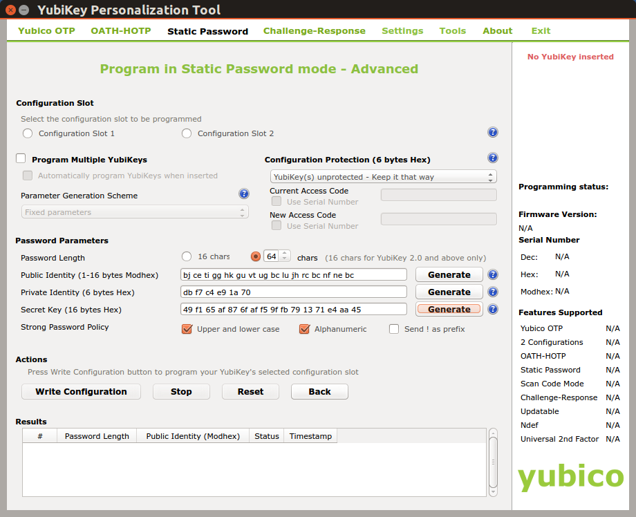
Example 1: YubiKey NEO static key
Start the YubiKey Personalization Tool and select `Static Password` and then `Advanced`.
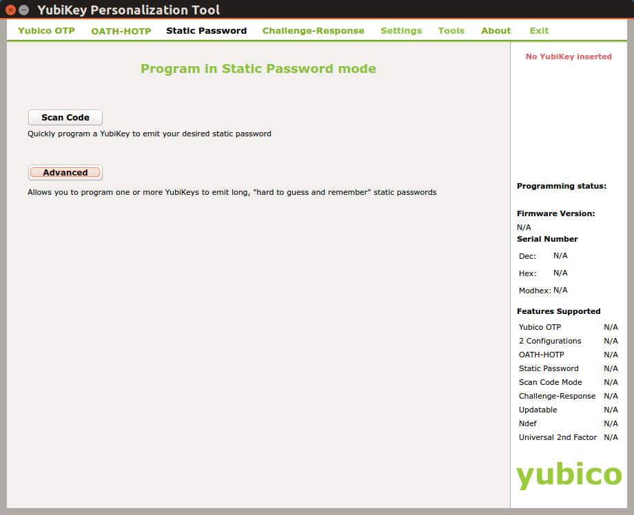
To create a 64 character static key set `Password Length` to `64`. Then click a few times on the `Generate` button of each `Public Identity`, `Private Identity` and `Secret Key`. Check `Upper and lower case` and `Alphanumeric` checkboxes to ensure that the key will include uppercase, lowercase and numbers. Deselect `Send ! as prefix` as a leading ‘!’ is not needed for the key.
Select the configuration slot (1 for short key press and 2 for long key press on YubiKey NEO) you want to use for this key and click `Write Configuration`.
Close the personalization tool and open a text editor or word processor. Press the button on the YubiKey (long or short depending on the selected configuration slot above) and see how the YubiKey types the key into the text editor or word processor.
This key needs to be converted into hex values which can then be used as `key_bytes` in `config.h`.
On linux this can be done with the command:
echo -n ”this-is-the-key-string” | od -A n -t x1
Windows users can use the `certutil` utility. Save the key to a text file (e.g. key.txt) then use `certutil` to convert this text file to hex:
certutil -f -decodehex key.txt key-hex.txt
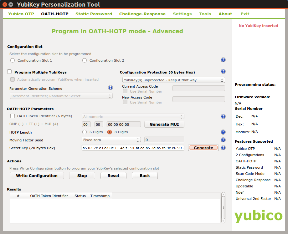
Example 2: YubiKey NEO HOTP key
Select `OATH-HOTP` in the YubiKey Personalization tool.

Don’t use an OATH Token Identifier, select 6 or 8 digits for the HOTP length and press a few times generate to generate the random secret key. `Moving factor seed` specifies the counter with which to start. To start with a counter of 0 specify `Fixed zero`.
The length, counter and key bytes are then configured using `config.h` as described above.
Known problems and limitations
Configuration
SL is not very easy to configure as the used Arduino provides not enough resources to implement full reconfiguration functions. But I think this is not really a problem as missing configuration functions when running in lock mode provide less attack surface.
Performance
SL can handle multiple keys (as long as flash is available). When a key is provided by an USB token all keys are searched linearly in order as they are configured in `config.h`. This means it takes longer for SL to validate a key the farther away from the flash start it is located. Also a large counter tolerance for HOTP keys slows down verification process as the number of tolerable keys must each be calculated. Practice tests have shown that ~5 HOTP8 keys (YubiKeys configured with slot 1) provide good results width about 1 sec to unlock.
Memory consumption
Enabling additional options in `global.h` like serial user interface or debugging output not only providers more attack surface but also reduces available memory resources significantly. These options are normally not used for standard operation. Ensure that after compiling at least 730 bytes are available for local variables (shown in console output). Otherwise you might notice wrong behavior (e.g. long 64 byte static keys might no longer be recognized). Below 700 bytes no key type will work!
Todo’s, ideas
- battery monitor and warning on low voltage when SL powered by batteries
- support for rechargeable batteries and charger circuit
- additional over/under voltage/power protection
- optional activity logging on serial port or memory (flash, SD-Card)
- developing a protocol for the two unlock signals understood by the unlock actuator instead of just setting both signals to High for unlock
- developing a lock picking safe unlock actuator
Critics, comments and frequently asked questions
This section tries to give some answers and thoughts on questions and comments I received about SL. Feel free to use the comment function here or at Hackaday.
- StickLock is not a WHOLE lock!!!
- compared to a physical lock where authorization logic (the bolts and springs matching the key) and unlock actuator (the cylinder and latch) are combined into one unit, StickLock represents only the authorization part. The two StickLock signals Device-Valid and Unlock tell the unlock actuator when to release the lock. That means while SL could be secure the used actuator could still be vulnerable to “paperclip” hacks. In that sense its wrong to state SL is more secure then an ordinary lock.
- Why not use some wireless technology like NFC?
- Because sticking a physical key into a lock simply provides less attack surface compared to wireless technology which could be (theoretically) sniffed.
- USB is a dumb idea!!!
- Because of what? An USB token has the same usage vulnerabilities like a classic key. It can be lost or stolen. Most of the standard physical locks used in lockers (except high security lock types which costs far more then most whole lockers) can be easily unlocked (assuming someone has the right lock picking tools and knowledge). Using USB as a lock could be more secure. Using a maximum of 64 bytes key IS
almostunbreakable with trying all possible combinations. Sure someone could use a UsbKill on StickLock but all he gets is a dead lock (much the same like pressing StickLocks clear switch). - Used correctly StickLock is almost (as nothing is) unbreakable
- enclosed in a sealed, resin filled steel case with screw terminals for LEDs, switches and power
- installed inside steel locker not directly attached to locker wall
- signal lines (Valid Device, and Unlock) must both be High to trigger unlock actuator (not specified, could be anything and is not part of this project)
- both unlock signal lines must be routed via different physical paths inside locker to unlock actuator
- external power supply to StickLock could be another attack surface
- over power will destroy StickLock rendering it useless
- lowering power supply provoking a BrownOut where SL could behave undefined must be handled by SLs power stabilizer and processor reset circuit
- Because of what? An USB token has the same usage vulnerabilities like a classic key. It can be lost or stolen. Most of the standard physical locks used in lockers (except high security lock types which costs far more then most whole lockers) can be easily unlocked (assuming someone has the right lock picking tools and knowledge). Using USB as a lock could be more secure. Using a maximum of 64 bytes key IS
- Using USB provides more attack surface!!!
- How? StickLock just understands a very limited set of the USB HID protocol everything else is ignored. All tests so far have shown that it is not possible to trick StickLock to set both unlock signal lines to High by either physically overloading/destroying the USB port or trying to bring it into an undefined state by introducing invalid USB protocol responses. Either the Arduino resets or hangs (both do not trigger an unlock)
- SL’s fallback of just being dead and keeping things locked on clear-switch or when destroyed as described above is a bad idea!!!
- This depends on what should be locked. I personally think its better SL stays locked in any failure case and I also would argue against a second non SL locking mechanism as described above at the clear-switch even if that means I must use a welding torch to get back my locked things. I agree there are no locks which could not be opened but the longer the time is it takes to break into it the better it is.
Resources
The Arduino IDE code for StickLock can be found on GitHub
Credits
- The SHA1 code from: https://github.com/Cathedrow/Cryptosuite
- The USB host library from: https://github.com/f … /USB_Host_Shield_2.0
License
StickLock is copyright by Richard Prinz