A PIC based DDS module
Table of contents
Purpose
How to produce analog frequencies with digital microcontrollers? Have you ever
had this problem? A while ago I had it. So I started to learn how to do it.
Here are results of this learning process. To start there are some realy good
resources available on the internet as well there are some good books.
For the basics look at:
So how can it be done using a simple PIC 16F84. First of all all - don't expect
too much quality of the generated signals. I have simulated my PIC DDS
using this MatLab script (
http://www.mathworks.com/). Open the script as text in MatLab (or your
text editor) and change the parameters at the beginning according to your
needs. This script then generates the sine table (in decimal and hexadecimal
form) for the pic. Copy and paste the hexadecimal version directly to your program.
The script also produces two graphics. Figure 1. shows the difference
between the original calculated floating point sine and the rounded integer
(you have to zoom within MatLab to see the difference) and Figure 2.
shows the quality of the signal based on the frequency your PIC is running.
(The blue sawtooth curve just shows the value of an index into the sine
table and as you can see it represents a sawtooth function. This means you can
also very simply produce sawtooth signals)
The two images below show the results for a PIC 16F84 running at 4 MHz, a
sine table with 256 entries, 8 bit sine table values, a phase accumulator
width of 24 bit and an assembler loop of 28 instructions to output a sinetable
value.
% ----- USER CONFIG -----

TableSize = 256;                % number of elements in sinetable
Floop = 28;                     % number of instructions per DDS loop
Freq = 1000;                    % wanted output Frequency
AccWidth = 3;                   % accumulator width 3 Bytes
fXtal = 4000000;                % main PIC16F84 osci
Image 1: MatLab Figure 1.
|
|
Image 2: MatLab Figure 2.
|
As you can see from this charts the quality of the output signal is not that
good but up to about 4kHz it's enough for most applications. If you use a
20 MHz PIC you will get better results and a bigger frequency range. Every 8 bits
of the selected sine table entry is put to port c of the pic. to get a analog
value a digital to analog converter is used. The output from this is a analog
signal at the frequency you have selected in the source of the PIC assembler
program. To reduce harmonics you can filter this signal.
The SineDDS assembler programm outputs a 1000 Hz signal when you press the
key the first time. It increments this signal in 100 Hz steps every time
you press the key until a frequency of 3000 Hz is reached. At 3000 Hz it rolls
over to 1000 Hz.
DISCLAIMER:
THIS CONTENT IS PROVIDED TO INTERESTED PEOPLE "AS IS" FOR NON COMERCIAL
PURPOSE ONLY. UNDER  NO CIRCUMSTANCES I AM RESPONSIBLE  FOR ANY DAMAGES
TO  YOUR RADIO, PC OR OTHER  EQUIPMENT. THIS  DEVICE  WAS TESTED  UNDER
DIFFERENT  CONDITIONS   AND  UNTIL  NOW  IT  WORKS   WITHOUT  PROBLEMS.
Schematics
As you can see in the schematic I use an old ZN426 D/A converter for this project. I's
faily old and I think no longer manufactured. But you can use any other 8 bit D/A converter
instead. Just connect all pins from the PIC port B to the corresponding inputs of the D/A
(PIC B0 to D0 of the D/A, B1 to D1 .....). The output of the D/A converter can be filtered
and/or amplified using standard OpAmps. Filter and amplifier are not shown in the schematic.
If you dont have a D/A converter at hand you can even use a R-2R resistor network. More
infos on that can be found in
Microchip Application Note number AN655.
Image 3: PIC DDS schematic
The PCB
There is no PCB available for this project. It was intended just as a proof of
concept and prototyped on a breadboard. See the pictures.
Software
These are the PIC 16F84 assembler listings for the DDS. They are
in Microchip MPASM (MPLAB) format. Just copy them into a directory,
compile SineDDS.asm and program the resulting SineDDS.hex file into the PIC.
Tools.h, Tools.asm - general tools
SineDDS.asm - main routines of the DDS
Or download all of these in this zip file.
To handle ZIP file look at WinZip
Pictures of the finished DDS module
As you can see on these pictures all 8 pins of PIC port B are connected to the
D/A converter ZN426 and the output of this is connected to the PC's soundcard.
Now you can start some testsoftware to measure the signals generated.
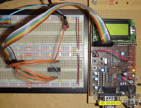
Image 4: PIC DDS prototype
Notes & Comments
Below are two spectrum graphics. It is a comparison between a 1000 Hz signal
generated with this PIC program and a 1000 Hz signal gerated with my
AD9835 DDS Module.
Image 5: PIC DDS 1000 Hz spectrum
Image 6: AD9835 DDS Module 1000 Hz spectrum
There is some room for expansion in this project. You can for example add
functionality to set the frequency serialy via two unused pins on port A.
With this functionality you have a NCO Numericaly Controlled Oscillator)
you can control for example with your pc or with another PIC.
Another possible extension would be to use two frequency registers. As you
meight see on the spectrum analyser when pressing S1 to switch to another
frequency there is a short interruption of the signal producing a lot of
unwanted harmonics. To overcome this you can use two frequency registers.
You can set one while the other is still at the previous frequency and
producing output. Then when the second register is set you just swap
the two. The same concept is used in DDS chips. See my
AD9835 Module Page
(and the PIC source there) for more infos.
73, OE1RIB