Super Simple PIC 16x84 Development Board
Table of contents
Purpose
When developing devices with the popular PIC 16x84 from Microchip you will sooner or later need
a testboard. This board can be used for this purpose. It's equiped with 2 keys, 4 leds, a
RS232 interface and a socket for a serial eeprom. Using jumpers it can be configured in some
ways. There is also a prototyping area available on the board which could be used for custom
extensions. This was used to add a LCD as you can see on the pictures below.
Jumper description:
- RS232 RX/TX
Enables/Disables RX/TX on Port A0/A1
- RS232 Power
When set the board is Powered by the RS232 DTR/RTS pins
- A0 Led
Enables/Disables a Led on Port A0
- A1 Led
Enables/Disables a Led on Port A1
- A2 Led
Enables/Disables a Led on Port A2
- A3 Led
Enables/Disables a Led on Port A3
- Keys
Enables/Disables Pushbuttons on B0/B1
- EEPROM
Enables/Disables a serial EEPROM on A2/A3
A2 - SDA
A3 - SCLK
DISCLAIMER:
THIS CONTENT IS PROVIDED TO INTERESTED PEOPLE "AS IS" FOR NON COMERCIAL
PURPOSE ONLY. UNDER  NO CIRCUMSTANCES I AM RESPONSIBLE  FOR ANY DAMAGES
TO  YOUR RADIO, PC OR OTHER  EQUIPMENT. THIS  DEVICE  WAS TESTED  UNDER
DIFFERENT  CONDITIONS   AND  UNTIL  NOW  IT  WORKS   WITHOUT  PROBLEMS.
Schematics

Image 1: Schematic of the Super Simple 84 Development Board
The PCB

Image 2: The PCB

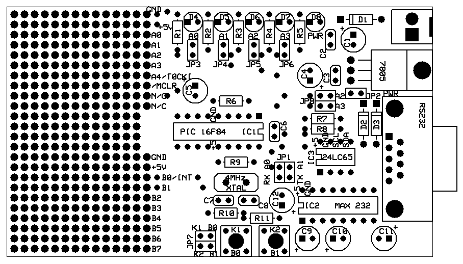
Image 3: Component positions
You can download a PDF File with the schematic and the PCB here.
If you
dont have the Adobe Acrobat Reader installed on your machine you can find it here

Pictures of the finished Development Board
Here you can see how the board looks during different stages of the building process
and how it looks when it's finished. A picture says more than thousand words.

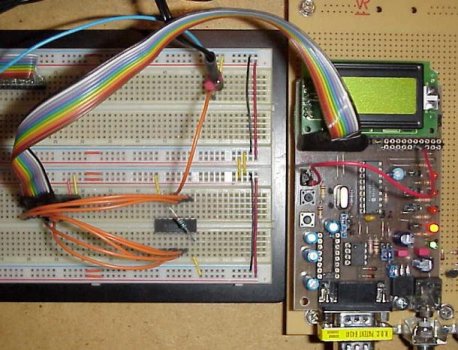
Image 4: The finished PCB with all components ...

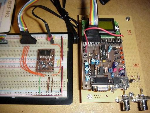
Image 5: and again
Notes & Comments
Credits
If you have any comments or sugestions just drop me a line.
73, OE1RIB


