RX2635H using external oscillator and serial port
Monday, April 6, 2015
Now that it’s possible to write custom firmware for a Walkera Hoten-X RX2635H-D receiver it’s time to try to access the various components on the ATMEL XMEGA32A4 based receiver board. First thing was to blink a LED which was quite simple. But for easier development there must first be a more user friendly way interact with the board. Fortunately there is a serial port available. It is normally used to upload new firmware and as additional channel for controlling e.g. a camera in the original Walkera firmware.
This post is part of a series
- Flashing new Firmware to Walkera RX/TX without UP02
- Decrypting receiver firmware
- Walkera receiver components
- Hello World firmware for the RX2635H board
- Serial port and external 16MHz oscillator (this post)
- Using the ITG-3205 mems gyro
- Walkera UP02 software clone: UP42
- Walkera RX2635H as generic development board?
- Walkera USB port
- Walkera + Arduino = Walkino
The used serial port is the second serial port on PORTD on pins PD7 and PD6. They are connected to connectors J4 (PD7) and J3 (PD6).Connect PD7 which is XMEGA transmit (TX) to PC receive (RX) and PD6; XMEGA receive (RX) to PC transmit (TX). The XMEGA uses 3V so dont connect it directly to your PC but instead use a level converter like a MAX3232 to handle a real serial ports 12V. The colors blue and yellow correspond to the colors used by the Walkera upgrade tool UP-02. More infos on that topic can be found here.
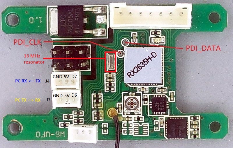
Also the external 16MHz oscillator should be started to run the processor faster and to calculate correct serial baud rates. Per default when the XMEGA starts it uses it’s internal 2MHz oscillator so the 16MHz one available on the board is not used. To use it the external oscillator must be anabled and the configuration has to be changed. See the function setupOsc() for more details.
Now calculate and set the correct baud rate, parity and stop bits (9600 baud, no parity and 1 stop bit in our example) to initialize the port. This is done in function setupSerial().
The simple example program just sends a prompt to the PC asking the user to press a key and waits until he does so. Then it prints the received character and asks again. It’s a simple test to show that the serial port is working as expected. This example does not use interrups for receiving data but instead just blocks the whole program.
#include <avr/io.h>
char b = 0;
void setupOsc(void)
{
    //16MHz external crystal
    OSC_XOSCCTRL = OSC_FRQRANGE_12TO16_gc | OSC_XOSCSEL_XTAL_16KCLK_gc;

    //Enable external oscillator
    OSC_CTRL |= OSC_XOSCEN_bm;

    //Wait for clock stabilization
    while(!(OSC_STATUS & OSC_XOSCRDY_bm));

    // Selects clock system as external clock
    // through change protection mechanism
    CCP = CCP_IOREG_gc;
    CLK_CTRL = CLK_SCLKSEL_XOSC_gc;
}
void setUpLED(void)
{
	// PD4 = LED output
	PORTD_OUTSET = PIN4_bm;
	PORTD_DIRSET = PIN4_bm;
}
void LEDon(void)
{
	PORTD.OUTCLR = PIN4_bm;
}
void LEDoff(void)
{
	PORTD.OUTSET = PIN4_bm;
}
void setUpSerial(void)
{
	// PD7 = RS232 TX output
	PORTD_OUTSET = PIN7_bm;
	PORTD_DIRSET = PIN7_bm;

	// PD6 = RS232 RX input
	PORTD_OUTCLR = PIN6_bm;
	PORTD_DIRCLR = PIN6_bm;

	// calculate 9600 baud
	// BSEL =
	//   (16000000 / (2^0 * 16 * 9600) - 1 = 103,1666
	//   BSCALE = 0
	// FBAUD =
	//   (16000000 / (2^0 * 16 * (103 + 1)) = 9615.384
	USARTD1_BAUDCTRLB = 0; //Just to be sure that BSCALE is 0
	USARTD1_BAUDCTRLA = 0×67; // 103

	// Disable interrupts, just for safety
	USARTD1_CTRLA = 0;

	// 8 data bits, no parity and 1 stop bit
	USARTD1_CTRLC = USART_CHSIZE_8BIT_gc;

	// enable receive and transmit
	USARTD1_CTRLB = USART_TXEN_bm | USART_RXEN_bm;
}
void sendChar(char c)
{
	// wait til DATA buffer is empty
	while( !(USARTD1_STATUS & USART_DREIF_bm) );

	USARTD1_DATA = c;
}
void sendString(const char *text)
{
	while(*text)
		sendChar(*text++);
}
char usart_receiveByte(void)
{
	while( !(USARTD1_STATUS & USART_RXCIF_bm) );

	return USARTD1_DATA;
}
int main(void)
{
	char c;

	setupOsc();
	setUpLED();
	setUpSerial();

    while(1)
    {
		sendString(”Enter a character\r\n”);

		c = usart_receiveByte();
		sendString(”Character was:”);
		sendChar(c);
		sendString(”\r\n\r\n”);

		if(b) LEDon(); else LEDoff();
		b = !b;
    }
}
You can download the complete AVR Studio solution here.