Raspberry PI power plug case
Monday, March 23, 2015
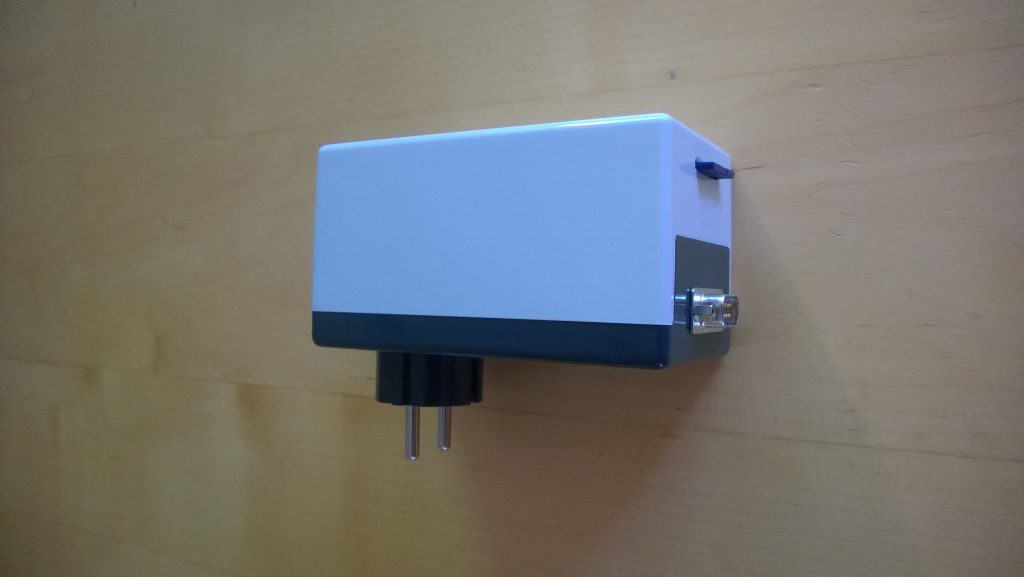
This post describes building a compact system based on a Raspberry PI inside a power plug much like the DreamPlug or others.
Managing and controlling things with a Rasperry Pi is common these days. The only problem in most situations is finding a suitable case. It shuld be compact, containing all necessarry parts and easy to modify. The Rasperry PI is not very suitable for installing it in standard cases due to it’s connectors. So there are lots of specialized cased from plastic or wood or metal. This situation has changed a little with the second generation of the PI but it is still not so easy to find the right case for a PI project.
The following text describs a way of installing a Raspberry PI including a power supply and extension board in one compact plug case.
These components are selected so that they fit very well together. Others meight also work but you have to check.
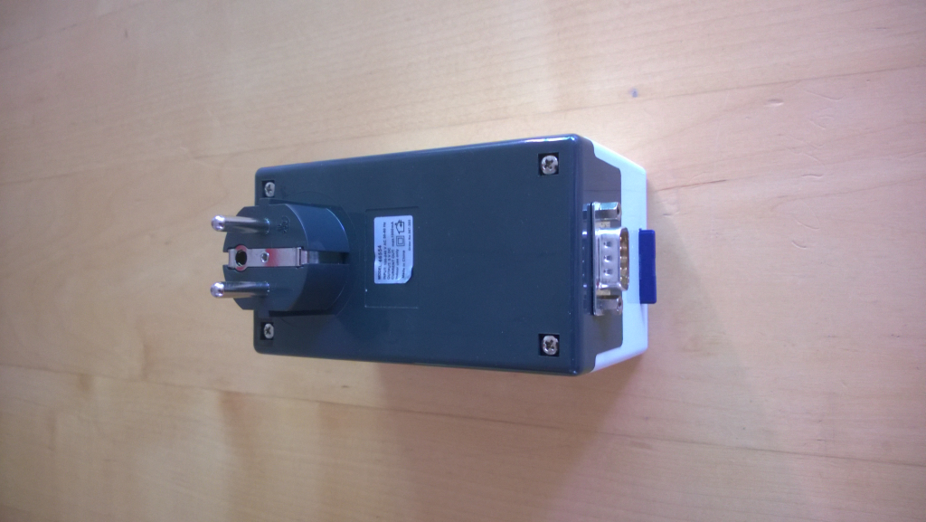
Case BOPLA SE 435 E/CEE - 9016
Order #: 43435001 or 43435009
Dimensions: 120 x 65 x 66
Source:
Conrad 521540 / 4016138521542
Price: ~25,00 EUR
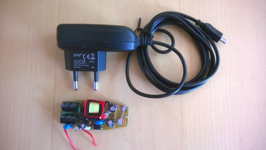
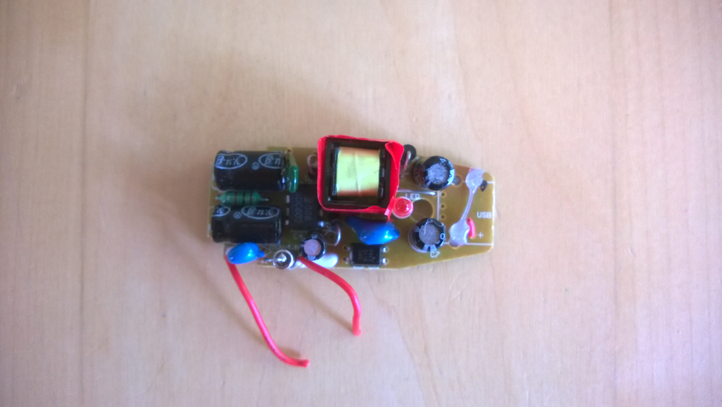
5V USB power supply GOOBAY TRA Micro-USB 1A
Order #: 46554 or 46600
Dimensions: 60.5 x 22.8 x 71
Source:
Conrad 646800 / 4040849465543
Price: ~7,00 EUR
An Edimax EW-7811Un USB WiFi dongle is used to provide network access to the Raspberry PI.
The extension board (from another post in my blog) provides a RS232 for console access, 3V and 5V I2C ports and a real time clock (RTC).
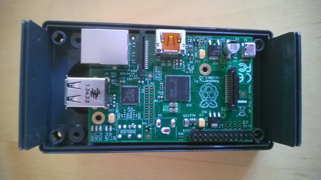
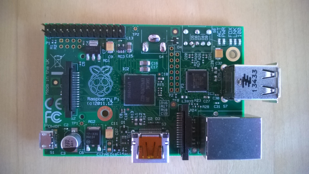
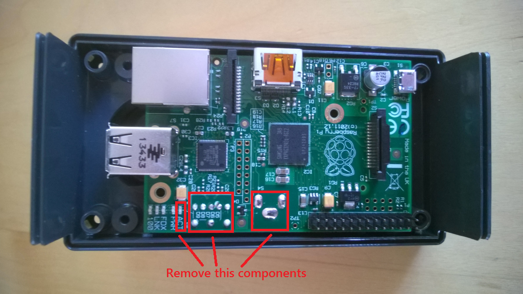
Start by removing (desoldering) the video and audio jacks from the Raspberry PI board because they stick out the PI board so it won’t fit inside the case.
After this the Raspberry PI fits perfect inside the case.
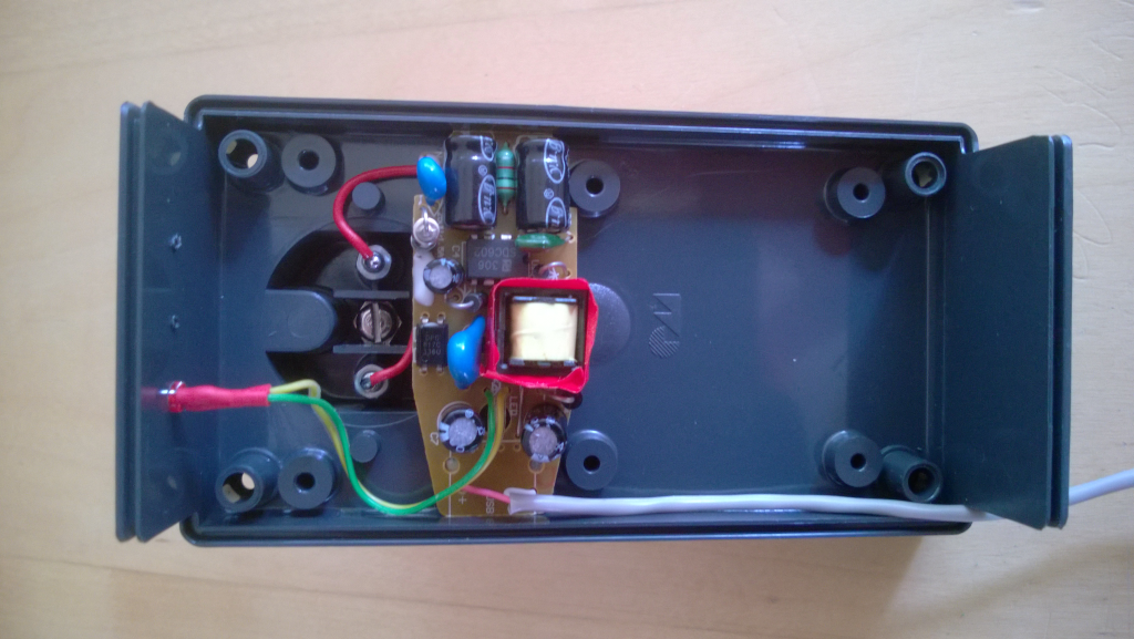
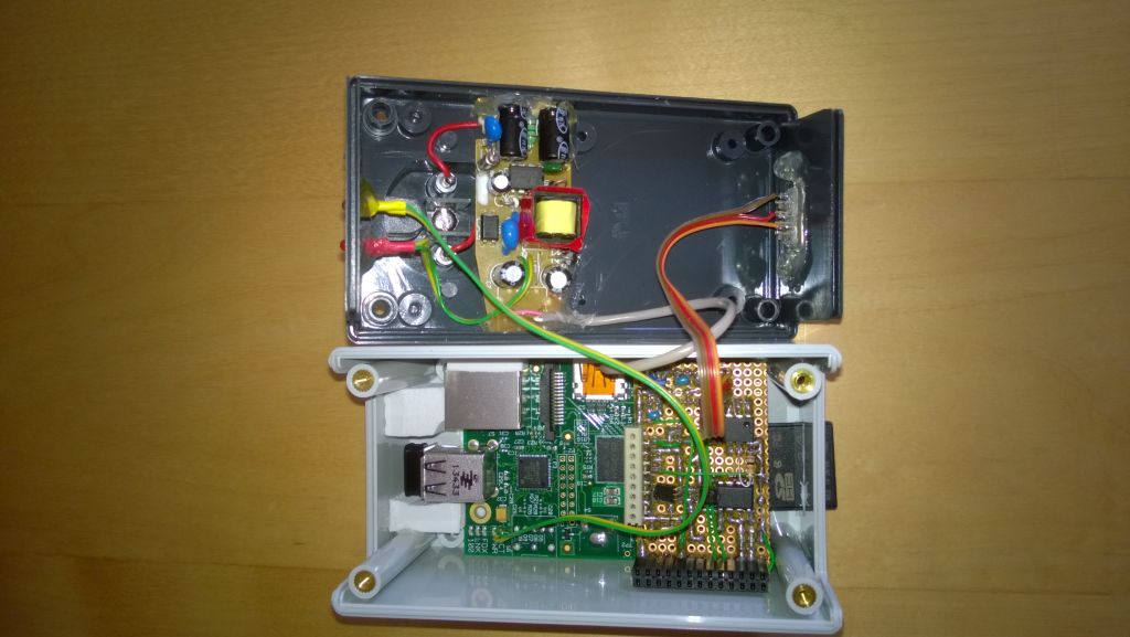
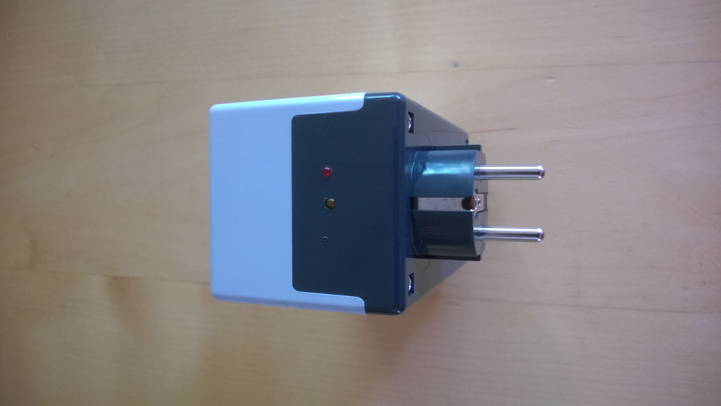
Unscrew the 5V USB power supply (just 1 screw under the sticker). As shown on the picture the power supply board fits also nearly perfect in the case. Mine was 1mm too big but using a feile it was fixed in minutes. Connect the power LED from the power supply using some wires to a LED in the case. This way there will be visual feedback if power is available to the PI. Next connect the 5V and ground lines from the supply to the PI. This can be done either using an USB connector, via the GPIO pins or by soldering the wires directly to the PCB.
The activity LED from the PI is also connected to a LED in the case for status display.
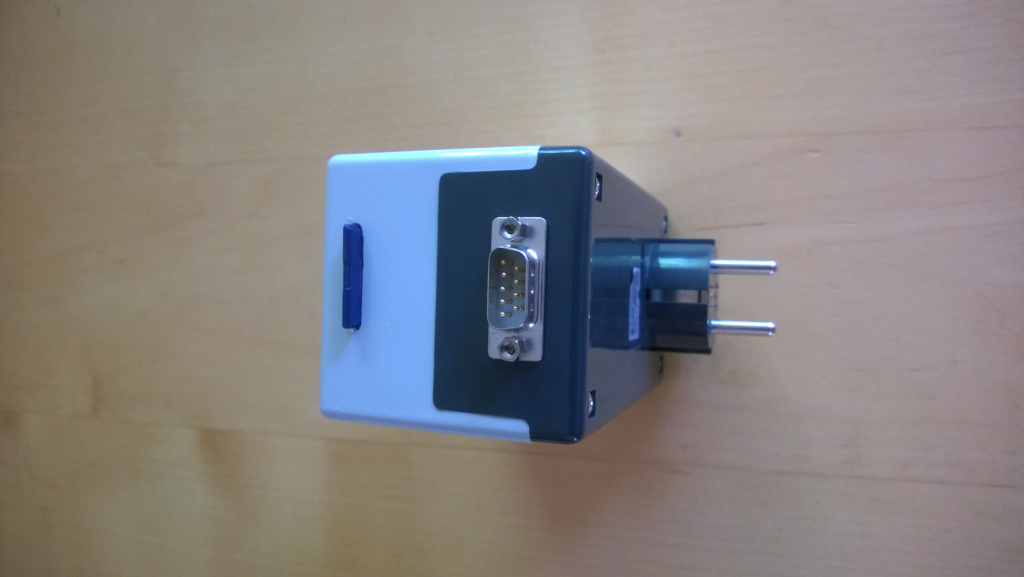
The PI itself is hold in the top part of the case using a little hot glue. A DB9 connector is used for RS232 signals to the outside world (Pins 2,3 and 5). Unused RS232 pins on this connector can be used for I2C or other signals. I used it for 5V and 3V level I2C.
The USB WiFi dongle is completely inside the case (as well as the whole USB port). If you need this type of connectivity you must cut some holes into the case. The same applies for the SD-Card. If you use a short one it will fit inside the case. I prefere a full size card so that I can change the OS on the fly.
Using Raspberry PI’s RS232 port and a switching device like described here it is possible to control devices like motors, heaters or airconditions via the WiFi of the PI.
Click on a picture for a larger view and more details.
WARNING:
AS THIS PROJECT CONNECTS DIRECTLY TO MAINS VOLTAGE (230V) BE ABSOLUTELY CAREFULL AND DOUBLE CHECK WHAT YOU DO. YOU MAY RISK YOUR HARWARE OR EVEN YOUR LIVE IF NOT DOING SO!! IF YOU HAVE ANY DOUBTS DONT DO THIS PROJECT. I AM NOT RESPONSIBLE FOR ANY ACCIDENTS OR DAMAGES!!