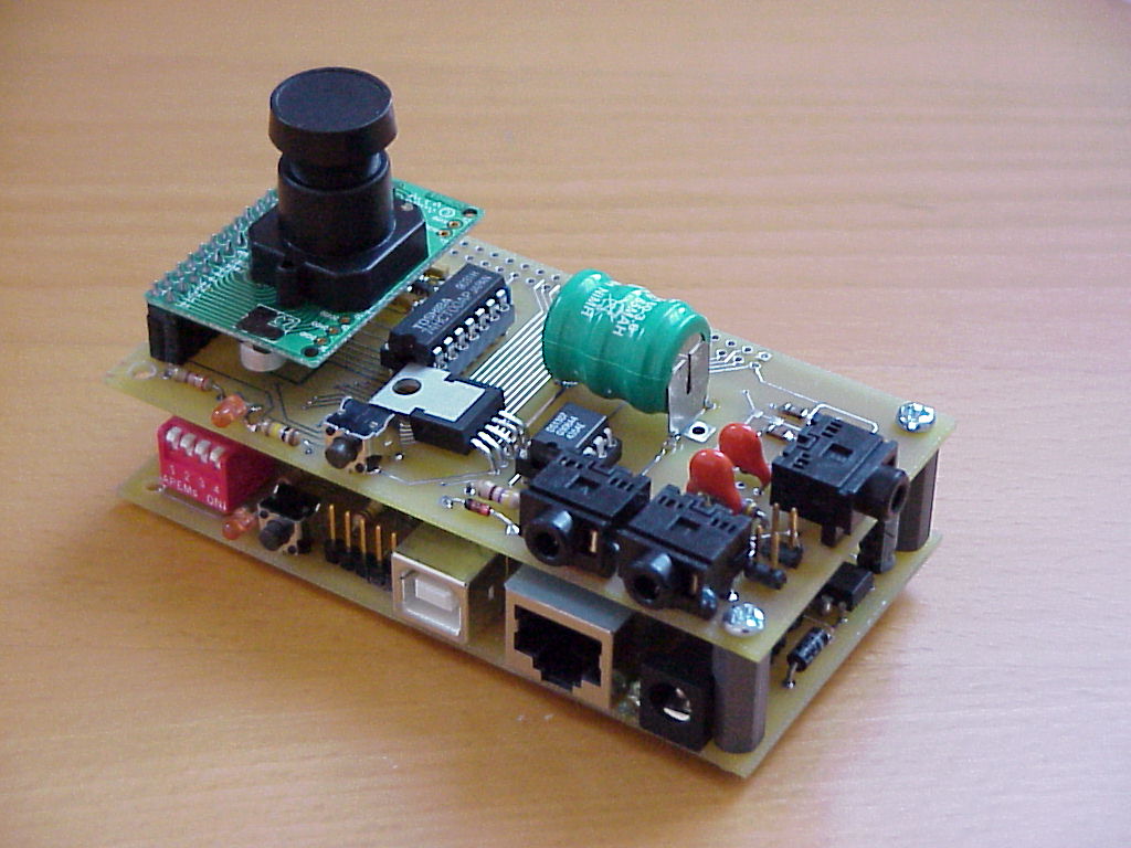
 The (nearly) finished SSTV System |
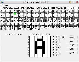
 An example picture sent by this SSTV system |
The (nearly) finished SSTV System |
An example picture sent by this SSTV system |
DISCLAIMER

THIS SITE  INCLUDING ALL  ITS CONTENT  (TEXT, PICTURES,  BINARIES ETC.)  IS NOT
ALLOWED TO BE  USED IN CRIMINAL OR  ILLEGAL ACTIVITIES. IT IS FOR NON COMERCIAL
PURPOSE ONLY! I  AM IN NO WAY RESPONSIBLE FOR  ANY EXTERNAL CONTENT  POINTED TO
FROM THIS SITE.   UNDER  NO  CIRCUMSTANCES I  AM RESPONSIBLE  FOR  ANY  DAMAGES
TO YOUR RADIO, PC OR OTHER  EQUIPMENT. USE THIS  SITE  AND  ALL OF ITS  CONTENT
AT YOUR  OWN  RISK! BY USING  THIS  SITE  AND  ITS  CONTENT  YOU HAVE  ACCEPTED
THIS DISCLAIMER.
|
In the past there where already some devices with resonable size like the Kenwood VC-H1 which allows to be mobile SSTV QRV. But unfortunately they disapear from the market but maybe still available on eBay.
Despite of the fact that the presented SSTV system is very simplistic (just 3 buttons and 2 LED's) it has a lot to offer:
Due to the small form factor a dual sided board was necessarry however the usage of SMT parts could be reduced to only a few. The SSTV Board is connected to the CPU board vie connector BUS so that both boards build a stack.
| Version | File |
| Version 1.0 | sstv-v1.0.zip |
| Version 1.5 | sstv-v1.5.zip |
| Version 1.10 | sstv-v1.10.zip |
 |
 |
| Componen placement | PCB full view |
 |
 |
| PCB top side | PCB bottom side |
Following you will see the three menues/screenshots of the firmware which allows configuration, diagnostics and operation. After pressing Cc (uppercase and lowercase c you will be presented with the configuration dialog. First you should set your callsign and other station rfelevant parameters. Next connect the output on connector xxx to your PC's soundcard input and start your favourite SSTV software (e.g MMSSTV). After pressing p (lowercase p) your software should start picture reception and after a while you should see the transmitted picture. If this test was successfull you can connect the output to your transceiver and start some SSTV QSO's.
 Version: 001.010


 *** Main Menu ***

 t - Send a colorbar testpattern
 p - Take color picture and send it
 P - Take black and white picture and send it
 a - Start automatic mode, end with ESC
 A - Same as 'a' but with 'g' (10 seconds) during wait
 l - Resend last picture in color
 L - Resend last picture as BW
 i - Send the Station ID (OE1RIB) in CW
 1 - Send the picture statusbar in CW
 2 - Send the testpattern statusbar in CW
 c - Send interactive CW
 C - Configure system
 g - Wait 30 sec for GPS NMEA position
 D - Diagnostics
 ? - This helpscreen

 >
|
 *** Config Menu ***

 c - Configure system
 c - Set clock
 s - Show system status
 r - Reset system to defaults
 f - Upload font
 a - About
 ? - This helpscreen
 < - Back to Main Menu

 >
|
 *** Config Dialog ***

 Current time: 23.07.2010 21:30:11, Temperature: 033 C
 StationID: OE1RIB
 Send StationID after transmission (Y/N): Y
 Mirror camera image (Y/N): N
 Large (256 = Y) or small (240 = N) image: Y
 Key action: p
 Time (seconds) between pictures: 010
 Macros: %C-Call, %V-Ver, %T-Temp, %d-Date, %t-Time, %L-Lat, %l-Lon
         %D-Day, %M-Mon, %Y-Year, %h-Hour, %m-Min, %s-Sec, %p-Pic#

 --- Camera Picture ---
 Statusbar (N-none, T-top, M-middle, B-bottom): T
 Current Statusbar font size (1-3) : 1
 Statusbar format: %C %h:%m %L, %l, %p
 Current Statusbar color (RRGGBB):
         foreground: FEFEFE      background: 0051D7

 --- Test Picture ---
 Statusbar (N-none, T-top, M-middle, B-bottom): M
 Current Statusbar font size (1-3) : 1
 Statusbar format:     *** SSTV Bacon %C ***
 Current Statusbar color (RRGGBB):
         foreground: FFFFFF      background: 000000

 >
|
 *** Diagnostics Menu ***

 --- OV7620 Diagnostics ---
 c - Reset Camera
 C - Take picture
 D - Show registers
 P - Dump out picture

 --- NF Diagnostics ---
 0 - Turn tone oscillator off
 1 - Turn tone oscillator on
 k - Sends a 1000Hz test tone
 2 - send 1500Hz
 3 - send 2300Hz
 f - Enter Frequency Word (00:00-FF:FF)
 F - Enter Frequency Value (00-FF)

 --- System Diagnostics ---
 r - Reset RTC and start oscillator
 d - EEPROM Editor
 i - Scan I2C Bus
 ? - This helpscreen
 < - Back to Main Menu

 >
|
A few boards are available for building the SSTV system. Contact me for details.
A new, slightly modified board layout with a modified 3V regulator and a better circuit for loading the RTC battery is available. There where also some modifications on the firmware. The new version provides the follwoing features:
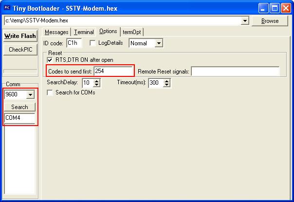
First flash "TinyBoot18F458.hex" with your favourite PIC programmer. After this use "FlashTool.exe" to flash "SSTV-Modem.hex" to the microcontroller. Ensure that "FlashTool.exe" is configured correct eg. port parameters and "Codes to send first".
The power consumption of the whole system (CPU board and SSTV board) is 90mA in idle mode and about 100mA while transmiting a picture.
The existing firmware allows to include additional data in transmitted pictures like date/time, callsign or the current temperature. Including the current position or synchronizing the clock from a GPS receiver would be beneficial. As there is only one serial port available in the sstv system this port has either to be shared or a second, software emulated serial port has to be created to connect both, a controlling system/console and a GPS receiver. As program memory is limited the decision was made to multiplex the existing hardware serial port by using a control signal on PORT B,2. receiver.
The following picture shows how this was done.

click for larger view
The GPS receiver must use the same serial parameters as the sstv system: 9600,N,8,1. The firmware looks for NMEA $GPGGA records and if it finds a valid one it syncs the internal RTC to the GPS time and extracts latitude and longitude infoamtion. These information can later be used in transmitted pictures using the %l and %L macros.
The "g" command switches to the GPS receiver and waits 30 seconds for valid date. If it receives valid data the command finishes. If you press/send ESC during this 30 seconds the wait is canceled.
There is also a new auto mode command "A" which automatically transmits color pictures with a configurable wait time between sends (same as the "a" command"). During this wait time the serial port is switched to the GPS receiver for another (additional) 10 seconds to receive valid location data. Other than with the "g" command this 10 seconds are fixed even if valid data is received before. This 10 seconds are ADDITIONAL to the configured wait time between sends.
Latitude and longitude information can be displayed in a pictures status bar by using the %L and %l macros. The macro "%p" is also new and inserts the current picture number (only usefull in automatic transmit mode otherwise the current picture number is 0).
 |
This paper can also be found in the german HAM Radio Magazine
"Funkamateur" at www.funkamateur.de, Issue 08 / 2007, Page 868, Title: "SSTV-Sendemodul auf Basis eines universellen PIC-Boards" |
73, OE1RIB