Flashing new Firmware to Walkera RX/TX without UP02
Tuesday, January 7, 2014
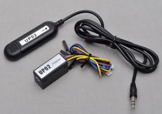 So you have a new quadcopter or transmitter from Walkera and found out that there is a new firmware available on the Walkera download site. Unfortunately you don’t have the UP02 and its companion UP02-Adaptor at hand but want to update regardless. In this blog post I’ll describe another way to update your device.
This post is part of a series
- Flashing new Firmware to Walkera RX/TX without UP02 (this post)
- Decrypting receiver firmware
- Walkera receiver components
- Hello World firmware for the RX2635 board
- Serial port and external 16MHz oscillator
- Using the ITG-3205 mems gyro
- Walkera UP02 software clone: UP42
- Walkera RX2635H as generic development board?
- Walkera USB port
- Walkera + Arduino = Walkino
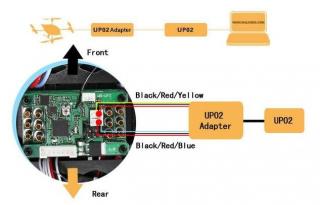 It turns out that the UP02 is a serial USB dongle and Walkera devices use a simple serial protocol based on XMODEM for firmware updates. The controller on the device uses a boot loader and it’s serial port to load new firmware into the controller. During power-up it checks for about 1 second if an UP02 is connected and if so goes into update mode.
The normal update procedure therefore is:
- disconnect the battery from the device
- connect the update tool to the device
- start the update utility on the PC
- bring your device into update mode
- if it’s a receiver just connect the battery
- if it’s a transmitter follow the manual (eg. for e Devo-7 press and hold ‘EXT‘ during power on)
The serial port on the controller uses 3,3 Volts, so DON’T CONNECT IT straight to your PC’s serial port. THIS WILL DAMAGE YOUR DEVICE. Instead use this simple circuit to connect it to a PC serial port:
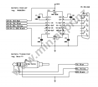
It is cheap, easy to build on e piece of perf-board and converts the PC’s serial port 12V (or 5V) to the receivers 3,3V. A little problem are the different connectors for receivers (especially on small receivers) which are not easy to get. But some shops offer cables with already mounted connectors for little money. The cable colors, black, red, blue and yellow correspond to the UP02 original cable colors where:
- black = ground
- red = power (3V3)
- blue = device send (TX)
- yellow = device receive (RX)
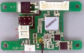
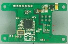
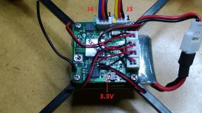
I have done my tests using a RX2635H receiver which is used in a Hoten-X. Technically ist should also work with other receivers like the RX2634H found in the Walkera Ladybird. It also possible to update Walkera transmitters with this method like the Devo-7. Connect the cables using the colored pin numbers as shown in the following images for the RX2635H and RX2634H:
RX2635H receiver Hoten-X
RX2634H receiver Ladybird
J3 and J4 share pin 1 (which is GND) so its enough to connect GND on only either J3 or J4. The 3.3V power could be connected to the receiver or to an external power source.
So use your favorite terminal program (like minicom or Tera Term) which must support XMODEM, select the serial port where you have connected the receiver, set it to 38400 baud, no parity, 8 data bits and 1 stop bit. Make sure the battery is disconnected from your controller. Now open the port in the terminal app and start sending ‘D‘ (character uppercase D). While doing this connect the battery to your receiver. It’s easier with a second person. If all goes well the LED on receiver should not light and he has sent back a ‘>‘ prompt (greater sign) to the PC. Now the receiver is in boot loader command mode.
The boot loader understands the following commands:
- D - ump - starts bootloader after power up
- Information - reads receiver information (type, model etc.)
- Quit - ends boot loader mode
- Flash - update receiver firmware
- ReadE2p - read eeprom, on transmitters read model config
- E2prom - write eeprom, on transmitters write model config
On the tested RX2635H receiver it was enough to just send the first character of the command. The following sections describe each command in detail. After sending a command the data for this command is transferred as 128 byte XMODEM blocks between PC and receiver. Each data block has a 3 byte header, 133 byte data and a 2 byte checksum. More infos about XMODEM can be found here, here and here. After issuing a boot loader command start an XMODEM send or receive action to read or write data to the receiver.
I have also tested this method with a Devo-7 transmitter. Although he understands the same commands the behavior is different. First there is no need to poll with ‘D’ like on a receiver. Instead it’s enough to press and hold the ‘EXT’ key during power on. As soon as the receiver display shows ‘– UPGRADE –‘ it starts sending the prompt character ‘>’. The transmitter boot loader also wants the full command and not only the first character. And the commands must be entered really quick between two following ‘>’. Manually using a terminal program there is no way sending commands to a transmitter by typing. Instead open an editor type the command and copy and paste it to the terminal. This works.
The following video shows how to send commands to the receiver and flash a new firmware.
Information
This command reads some information’s back from the connected receiver. These include the model name, available memory and other info’s. You can either send the whole command ‘Information‘ or just the short form ‘I‘. After issuing the command start an XMODEM receive and you should receive a 128 byte block with infos about the receiver. You can also test the the command without XMODEM by sending a ‘C‘ (character uppercase C) after the command. The receiver responds with a XMODEM block of data:
   01 01 FE 4E 61 6D 65   ...Name
3A 48 6F 74 65 6E 20 58  :Hoten X
20 76 31 2E 30 20 46 6C   v1.0 Fl
61 73 68 3A 20 33 32 4B  ash: 32K
20 45 32 70 72 6F 6D 3A   E2prom:
20 31 4B 20 54 6F 74 61   1K Tota
6C 4E 6F 3A 20 31 00 7C  lNo: 1.|
48 74 61 CD F4 D2 46 60  Hta...F`
DA 40 CD 88 94 4A 1B 7C  .@...J.|
48 74 61 CD F4 D2 46 60  Hta...F`
DA 40 CD 88 FF FF FF FF  .@......
FF FF FF FF FF FF FF FF  ........
               ...
FF FF FF FF FF FF FF FF  ........
FF FF FF FF F4 59        .....Y
0×01 0×01 0xFE is the XMODEM block header, followed by a 0×00 terminated (C) device information string:
- RX2634: Name:QR-Ladybird v1.3 Flash: 32K E2prom: 1K TotalNo: 1
- RX2635: Name:Hoten X v1.0 Flash: 32K E2prom: 1K TotalNo: 1
- Devo-7: Name: DEVO-7 Boot v1.0 Flash: 120K E2prom: 1024B TotalNo: 15n.
This information contains the name of the device, the version of the boot loader (or firmware?), flash size, eeprom bank size and number of eeprom banks.
After this follow some unknown data. The block is ended by 0xF4 0×59 which is the XMODEM checksum (CRC). To return to the boot loader command mode acknowledge this data by sending 0×06. The receiver should respond with 0×04. Send 0×06 again and the receiver will send its prompt ‘>’ and can now accept new commands.
Quit
This terminates boot loader command mode and brings back the receiver to normal operation. You will notice that the receiver led will not light when the receiver is in boot loader command mode. After the quit command the led starts flashing immediately. Just send ‘Q‘ (character uppercase ‘Q’) and you are done.
Flash
The key command to update your receiver. Initiated with ‘Flash‘ or just ‘F‘ the receiver starts sending ‘C‘ indicating that he is ready receiving a new firmware. Start an XMODEM upload with a firmware file. The receiver should answer with its prompt ‘>’ after upload.
I have not tested sending invalid content/files to the receiver. Be careful!.
ReadE2p
This command reads eeprom information’s from the receiver. It’s unclear to me what is stored in the eeprom on a receiver. On a transmitter in the eeprom banks the model configurations are stored. The command needs a parameter which specifies which eeprom bank (model memory) to read and is zero based. So the first bank is bank 0. Infos about the size and number of banks can be found in the response to the ‘Information‘ command. To read the first eeprom bank send ‘ReadE2p 0‘ or ‘R0 ‘ (on the Devo-7 to read model memory #15 send ‘ReadE2p 14‘) and start an XMODEM receive (or terminate the command with ‘C‘). If you have started an XMODEM receive you will get a file of the eeprom bank contents. If you sent ‘C‘ you must acknowledge each 133 byte XMODEM block with ‘0×06‘ until you get the ‘>’ prompt again. On my receiver specifying a wrong or even no bank number at all always results in the same 1024 bytes sent back from the receiver. Could be that in these cases the contents of the first bank is returned.
E2prom
This is the reverse of the ReadE2p command. This also needs a parameter specifying the eeprom bank. After issuing this command you can send a 1024 byte file using XMODEM which will be written to the specified location.
I have not tested what happens if you send more than 1024 bytes or try to write to invalid bank numbers!
Alternate receiver firmware
There is a good replacement firmware for Walkera transmitters available: Deviation(X). So why not do the same on the receiver side? More or less the tested RX2635H receiver is just like a big (Atmel XMEGA*A4) arduino and it should not be very hard to develop an alternate receiver firmware with more/other possibilities like the original one. The first step could be this blog post.
Update 25.3.2015
I wrote a new blog post about analyzing and decrypting the receiver firmware here
